The Path Panel
The Path panel is used when editing a path with the Node tool, or to combine shapes using various combination modes. To open the Path panel, select the Window - Path command.
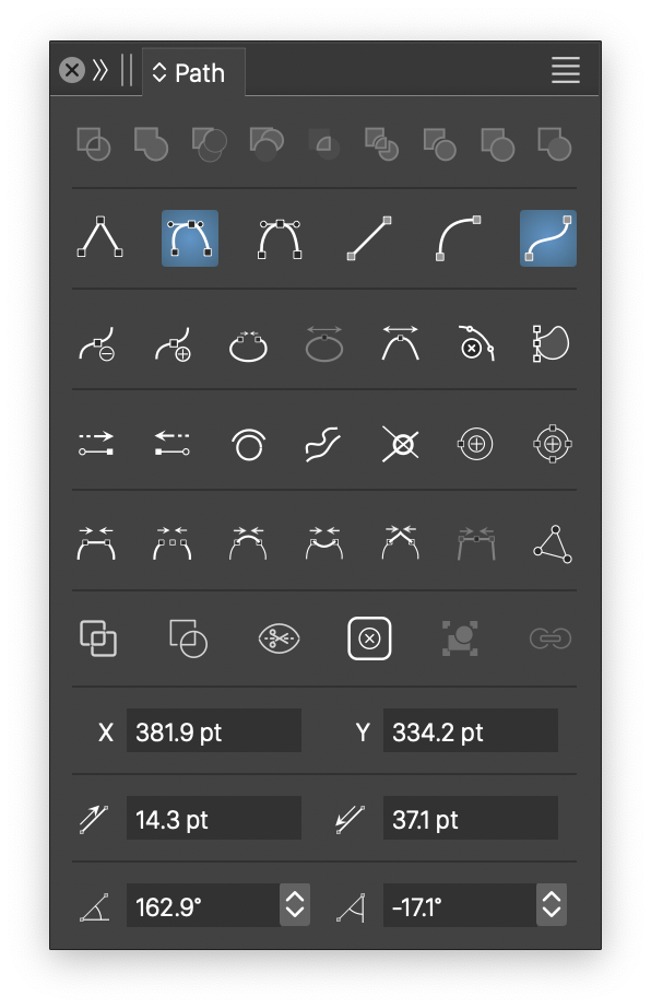
The Path panel.
The Path panel contains the following commands and fields (in order of appearance, from top to bottom):
The shape combination commands (first row) are used to combine two or more shapes using a shape combination mode. The combination mode of each button is show in a tool tip while hovering over the button.
Select two or more objects with shapes to be combined. Click on one of the icons in the top row of the path panel. The selected objects are combined into a single object with a shape that is a combination using the clicked operation. To create composite shapes (where the original shapes remain editable), hold the Option (Mac) or Alt (Windows) key and press the shape combination mode icon. In this case, the resulting object will have a composite shape, where both the original shapes and the combination mode can be changed later.
The content of the Path panel can be adjusted using the panel content (double up/down arrow) icon from the panel title. The features listed next are enumerated as they shown in the largest content of the Path panel.
The following combination modes are accessible from the Path panel:
 - Combine the selected shapes to create a combined path containing two or more sub-paths. The filling mode of combined paths can be winding or even-odd, selected from the Appearance panel.
 - Creates a union of two or more shapes.
 - Excludes the selected shapes from the bottom selected shape.
 - Excludes the top shape from the all other selected shapes.
 - Creates an intersection of two or more shapes.
 - Divide the shape into separate regions.
 - Trim overlapping shapes.
 - Merge overlapping shapes with the same style.
 - Create a boundary shape of the selected shapes.
The second row of commands from the Path panel are used to change the selected node and segment types. Nodes can be cusp, smooth or symmetric, while segments can be line, quadratic or cubic.
 - Change the selected nodes to cusp modes. Cusp nodes with not too large angles can have corner shapes.
 - Change the selected nodes to smooth modes. At smooth nodes, the path has a continuous curvature, changing the control point on one side will move the other side as well.
 - Change the selected nodes to symmetric modes. At symmetric nodes, the path has the same continuous curvature at both sides of the node. The control points of the node will be at equal distances from the node.
 - Convert the selected segment (with an inner point), or the segments after the selected nodes to line segments.
 - Convert the selected segment, or the segments after the selected nodes to quadratic curve segments. Quadratic curves have a single curvature control point.
 - Convert the selected segment, or the segments after the selected nodes to cubic curve segments. Cubic curves have a two curvature control point.
The third row of commands accessible from the Path panel are used to create, remove or break selected nodes in the edited path. These commands are active when there is a suitable node selected while using the Node editor.
 - Remove the selected nodes from the edited path.
 - Create new nodes at the selected inner location of a segment, or at the middle of the segment following the selected node.
 - Join two ending nodes of a path, closing the path. If the two nodes are from two different open paths, the two paths are joined into a single open path.
 - Open the closed path at the selected node, without moving the nodes.
 - Break the edited path at the selected nodes.
 - Join two paths by merging the selected nodes.
The fourth row of commands accessible from the Path panel contains additional path editing commands.
 - Retract the anchor point before the selected node.
 - Retract the anchor point after the selected node.
 - Reverse the direction of the selected path.
 - Simplify the selected path.
 - Rearrange the selected path according to the winding fill rule.
 - Insert a new node at the nearest extrema on the path.
 - Insert a new node at all extrema locations on the path.
The fifth row of commands accessible from the Path panel contains commands used to connect paths using various extension schemes.
 - Join shapes by connecting consecutive ending nodes.
 - Join shapes by positioning nodes between the ending nodes.
 - Join shapes by connecting with a smooth extension.
 - Join shapes by connecting with a cusp extension.
 - Join shapes by extending the curvature at the ending nodes.
 - Merge two consecutive selected nodes at the middle along the segment.
 - Connect the selected open paths at overlapping nodes.
The sixth row of commands from the Path panel can be used to intersect and change the shape of the selected objects.
 - Cut the path and separate at intersection points.
 - Cut with the last path at intersection points.
 - Cut the path into multiple sub-paths at cusp nodes.
 - Remove the shape of the selected objects (used to remove clipping paths of groups).
 - Assign a shape to the selected objects using the shape of the first selected object.
 - Link the shape of the selected objects to the shape of the first selected object.
Some of the commands accessible from the Path panel, are also available in the context panel, when the node tool is active.
The 7th row in the Path panel contains the X and Y coordinates of the selected node. These fields can be used to set exact positions to a node in a path.
The 8th row contains the length of the incoming and outgoing tangent vector at the selected node.
The 9th row contains the angle of the incoming and outgoing vectors at the selected node. The length and angle of the tangent vectors determines the curvature at the node of the incoming and outgoing segments.
The Path Panel menu
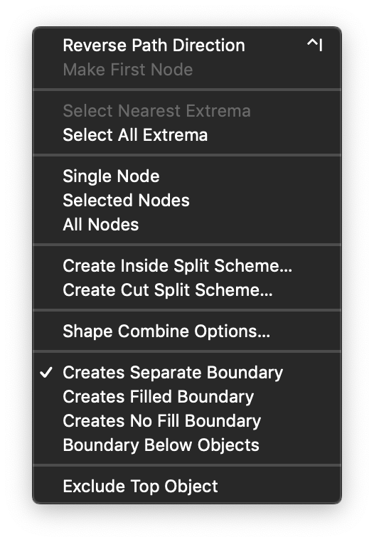
The Path panel menu.
The Path panel menu contains additional options of the path editing operations:
- Reverse Path Direction - Reverses the direction of the selected path.
- Make First Node - Shifts the path nodes to make the selected node the first along a closed path.
- Select Nearest Extrema - Select the nearest extrema location along the path.
- Select All Extrema - Select the all extrema locations along the path.
- Single Node - Show tangents for single nodes only.
- Selected Nodes - Show tangents for all selected nodes of the edited path.
- All Nodes - Show tangents for all nodes of the edited path.
- Create Inside Split Scheme - Create a shape splitting scheme using a set of closed shapes.
- Create Cut Split Scheme - Create a shape splitting scheme using a set of open shapes.
- Shape Combine Options - Edit the shape combination operator options.
- Creates Separate Boundary - Create new object when creating the object boundary.
- Creates Filled Boundary - Fill the boundary shape.
- Creates No Fill Boundary - Create a boundary shape with no fill style.
- Boundary Below Objects - Create a boundary shape below the selected objects.
- Exclude Top Object - Select the order of objects when excluding.