Gear Shapes
Gear shapes are parametric shapes with a user specified number of sides and other options. Gears can be used as object shapes, or building blocks for more complex shapes. In VectorStyler, the sides of a gear shape can be bent, allowing for more parametric shape options.
The properties of a gear shape can be edited using the Node tool or the Shape panel.
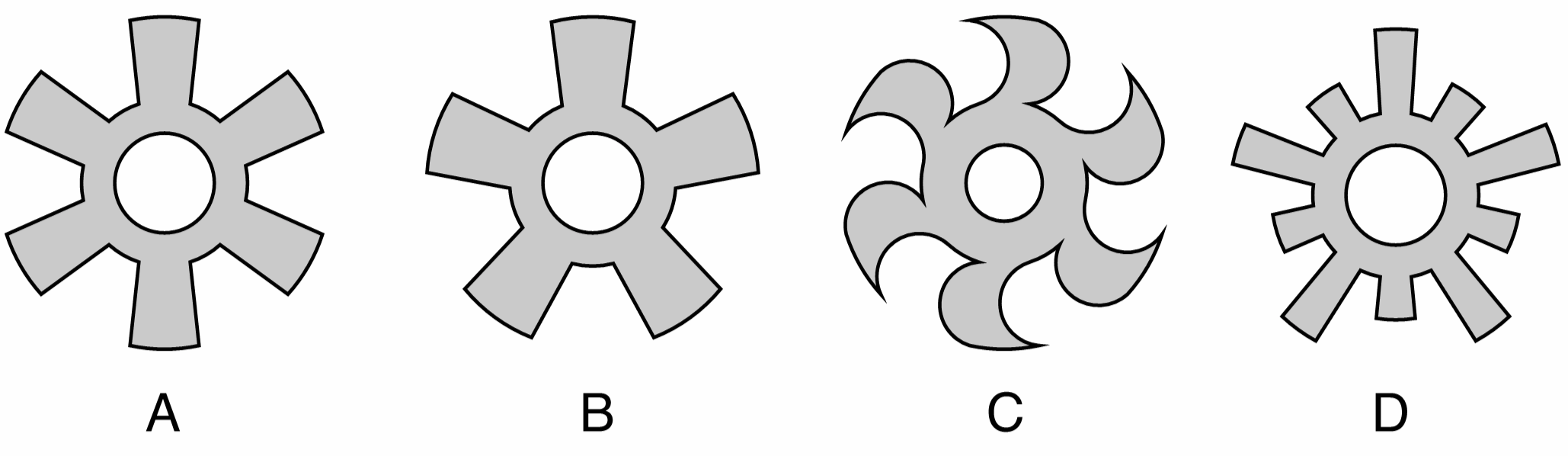
Gears with different properties: (A) a gear with six sides, (B) a gear with 5 sides, (C) a gear with bent sides, (D) a gear with 2 levels and 5 sides.
Drawing Gears
Gears can be drawn using the  Gear tool from the application toolbox. To draw a gear:
- Select the Gear tool from the toolbox.
- Press the mouse on a starting location on the canvas, this will be the center of the gear.
- Drag the mouse to set the gear radius and rotation.
- Hold the Shift key to restrict the gear rotation to user specified increments (45 degrees by default).
- Press the Up arrow key to increase the gear sides while dragging.
- Press the Down arrow key to decrease the gear sides while dragging.
- Release the mouse to create a gear with the selected radius and rotation.
If the document view is rotated, the gear shape will be drawn with the opposite rotation angle to the view.
The default gear options can be set by double clicking on the Gear tool icon in the toolbox. For example: the number of sides of the gear can be set numerically before drawing the gears.
To create a gear by setting the numeric properties of the shape, click at a point on the canvas. This will open the Gear view (described below) that contains all the gear shape properties. Set the required values and press Ok to create a new object with a gear shape.
Editing Gears
The Node tool can be used to interactively edit gear shapes:
- Select the object with a gear shape.
- Select the
 Node tool from the application toolbox.
 - A handle is shown at each inner and outer side, the outer corner, and the middle of each cog of the gear.
- Adjust the size and radius of the gear by dragging one of the outer side handles.
- Hold the Shift key to restrict the rotation to user specified increments.
- Hold the Control key to change only the radius and keep the angle fixed.
- Hold the Option (Mac) or Alt (Windows) key to change only the angle and keep the radius fixed.
- Adjust the bending of the gear sides by dragging a handle at the middle of a cog.
- Adjust the outer extent of the gear by dragging a handle at the outer corner.
- Adjust the inner extent of the gear by dragging a handle at the inner corner.
- Adjust the hole radius by dragging the handle on the hole circle.
- Press the Up arrow key to increase the gear sides.
- Press the Down arrow key to decrease the gear sides.
Gear Properties
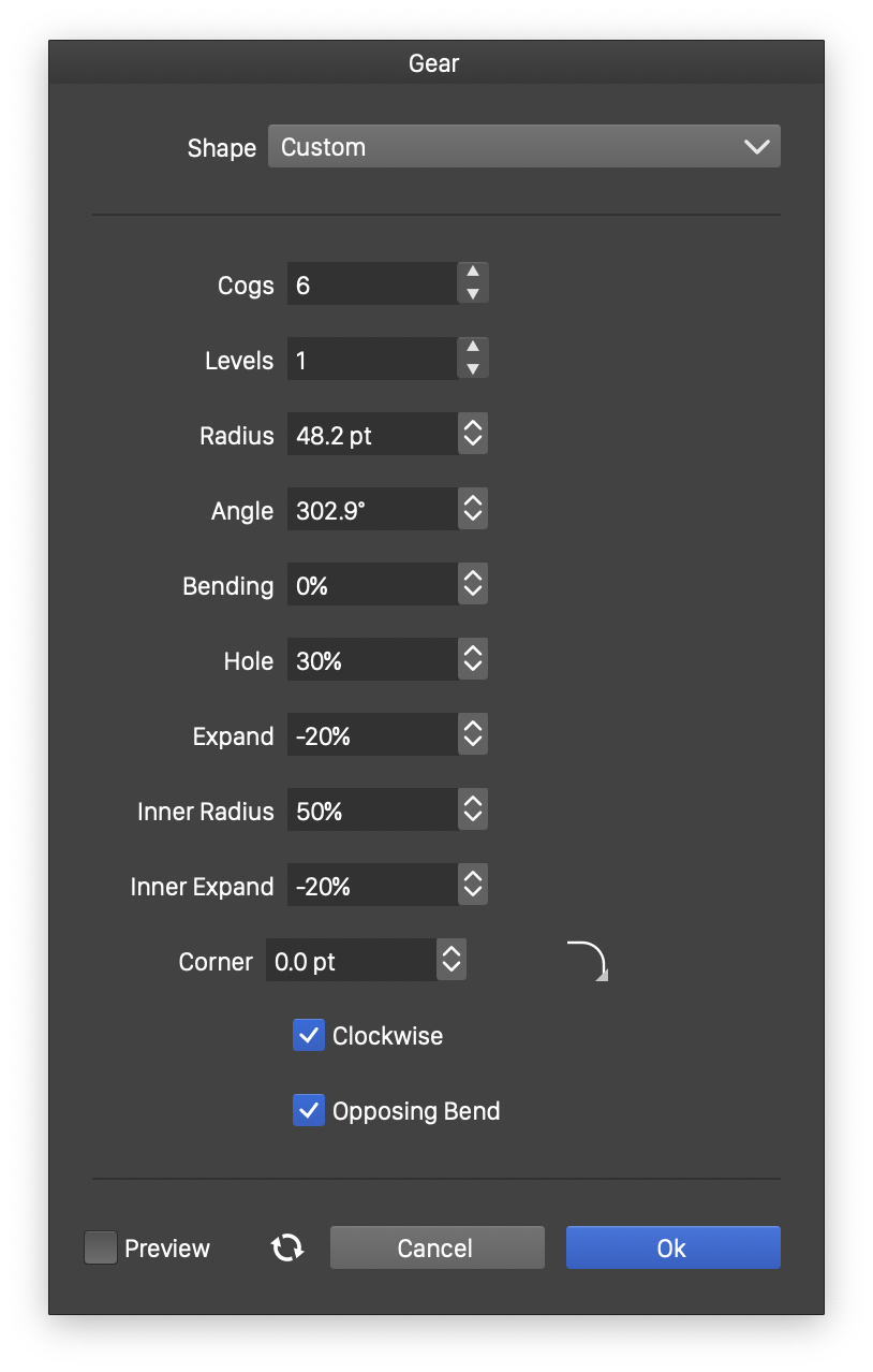
The Gear view.
The properties of a gear shape can be edited in the Shape panel when the shape is selected, or in the Gear view, either from the shape panel, or when editing a shape style.
The following properties can be modified for a gear shape:
- Cogs - Select the number of cogs in the gear on one level.
- Levels - Select the number of levels in the gear. By default, there are 2 levels, the inner and outer sides.
- Radius - Select the radius of the gear.
- Angle - Select rotation of the gear.
- Bending - Select the bending amount of the gear cogs.
- Hole Radius - Select the radius of the gear hole, relative to the gear radius.
- Expand - Select the size of the outer side of the gear cogs.
- Inner Radius - Select the radius of the inner side of the gear, relative to the gear radius.
- Inner Expand - Select the size of the inner side of the gear cogs.
- Corner - Select the corner size and select the corner shape.
- Clockwise - Set the gear shape direction to clockwise or counter-clockwise. The shape direction can be observed with the Node tool after converting the gear to curves.
- Opposing Bend - Select the gear cogs bending direction.