
Drawing Curves
In VectorStyler, a shape is a sequence of lines and curves making up an open or closed form that can be filled or outlined. When in its basic form (curves and lines) the shape is also called a path. A path can be edited using the node tool, by changing the location of nodes (endpoints of curves and lines), by dragging the handles of curve tangent segments, or by dragging the curves to change their shape.
In VectorStyler, shapes like rectangles, ellipses or polygons are parametric shapes, whose nodes are not immediately available for editing. When editing these shapes, the Node tool will edit the parameters of the shape (number of sides, arc angle, etc). To edit these shapes as paths, use the Convert to Curve command from the Object menu. After converted to curves, the parametric shapes are detached from their original parameters and can be modified as arbitrary paths.
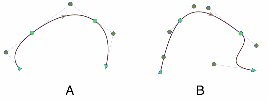
A curve segment type can be (A) quadratic or (B) cubic.
In VectorStyler a path may contain a mix of quadratic and cubic curves (as well as straight lines). The quadratic curves have a single tangent control node, while the cubic curves have two. Quadratic curves are used for example in some (but not all) types of TrueType and OpenType fonts. When converting a text shape using such a font to curves, the resulting paths will contain quadratic curve segments.
Shapes can also be generated from various geometric primitives, where the parameters of these primitives remain editable. In these cases, instead of editing a sequence of lines and curves, the shape is edited by changing the parameters of the geometric primitives. To obtain a path from a geometric primitive, use the Convert to Curves command. After converting to curves, the lines and curves making up the geometric primitives are revealed and become editable, but the parameter of the primitive are discarded.
Shapes can be created by drawing lines or curve segments, or by using the pencil tool to paint a shape.
The Line Tool
The  Line Tool is used to draw one or more objects consisting of lines only. The tool can be used to draw single lines, or a closed or open shape containing a sequence of lines.
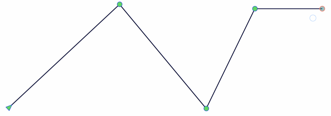
Drawing a shape containing a sequence of lines.
To draw the line, press the mouse at the location of the starting point. If snapping is enabled, the selected snapping options will apply to precisely position the line ends. Hold the mouse and drag the line end to the desired location. When the mouse is released, a new object with a shape consisting of a single line is created. The outline attributes of this shape are the same as the previously selected object outline attributes, or the current settings in the stroke panel.
The start of the line is indicated with an arrow node, while the end is a circle. To continue adding lines to the existing shape, press the mouse at the end of the line and drag the mouse to a new line ending location. This will connect a new line to the existing shape, without creating a new object.
While drawing lines, the Shift key can be used to constrain the line angle to increments of 45 degree (changeable in the application settings). Holding the Shift key before starting a new line and clicking will add the line to the selected open shape, even if not clicked at the last node. The shape consisting of lines can be closed by dragging the end of the last line close to the starting point.
While drawing lines, various snapping options may apply, positioning the line ends precisely. If the guideline snapping is enabled, the angle of the line can be restricted to be parallel or perpendicular to existing guidelines (even if not close to the drawing location), if the angle is close to the parallel or perpendicular angles.
The Pen Tool
The  Pen Tool is used to draw one or more objects with shapes consisting of curves (quadratic or cubic) and lines. The Pen tool is used for example to manually trace image contours (if Image Trace is not suitable) or to manually create special shapes. The resulting shape will be a path that can be edited using the Node tool.
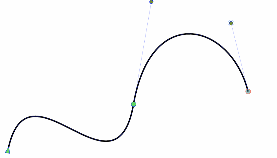
Drawing a shape with the pen tool.
To draw a path, press the mouse at the location of the starting point. Drag the mouse to draw the first tangent node. The pen tool will draw cubic curves. These can be changes to quadratic curves using the Node tool. To continue to draw the path, press the mouse at the ending location of the curve segment and drag the second tangent node. New curve of line segments can be added to the path by pressing the mouse to the ending location of the new segment and dragging the tangent node.
To draw with sharp corners, hold the Option (Mac) or Alt (Windows) key, and drag the tangent handle. This will not modify the final curvature of the previous segment.
To draw a quadratic curve segment, first press the mouse at the ending location of the segment, and then hold the Command (Mac) or Control (Windows) key, while dragging the tangent node. This will create a quadratic segment, with a single tangent node.
There are two modes to draw a line segment using the pen tool. The first mode is to just click at the ending location (releasing the mouse). This will add a line segment between the location and the last point of the path.The second mode is to press the mouse at a location and then press and hold the Control key. Dragging the mouse while the Control key is held will add a line segment to the path.
The various active snapping options will apply while drawing curve segments of a path. This includes the parallel and perpendicular angles to existing guidelines, if the guideline snapping is enabled.
An existing object consisting of an open path can be extended using the pen tool, by selecting the object, selecting the pen tool, and continuing the drawing process as described earlier.
The Pencil Tool
The  Pencil tool can be used to draw open or closed paths in a similar way as drawing freely with a pencil. As the pencil is dragged across the canvas, a set of point locations are collected. When the pencil is released, these locations are approximated as close as possible, using as few as possible cubic curve segments. The precision and smoothness of approximating the points using curve segments can be set in the application settings, or in the properties panel.
To draw paths using the Pencil tool, press the mouse (or stylus for tablets) at the starting location and drag according to the desired shape. The drawing will be indicated using a thin line. When the mouse is released, the new shape is created by approximating the drawing using the current smoothness settings.
It is also possible to include lines into the drawing. At any moment, while drawing, hold the Control key and drag the mouse. Instead of drawing along the locations, a line is drawn from the point of pressing the Control key to the current point. After releasing the Control key, the free shape drawing mode will resume.
Eraser Mode
The eraser mode of the pencil tool can be enabled using Eraser check box in the context panel, visible when the pencil tool is active. This enables the erasure of parts of paths between intersection points, by holding the Shift key and painting over the part to be erased.
The eraser mode can also be used to erase parts of existing shapes, if these are selected before the pencil tool is activated. In eraser mode, all shapes drawn with the pencil tool remain selected (to be available for erasing). To restart with an empty selection, press the Escape key.
It is important to remember, that when the Eraser mode is off, the pencil tool will not keep the previously drawn shapes selected. Only the most recently drawn shape is selected. This means that turning the Eraser mode on after creating a few shapes, the pencil tool will not be able to erase on these previously drawn shapes (they are not selected). In order to use the eraser mode of pencil tool on previously drawn shapes, use the pointer
tool to select these shapes, and then select the Pencil
To erase parts of shapes with the pencil tool, use the following steps:
- Select the objects to be used in erasing. The selected objects determine the intersection points.
- Select the Pencil tool.
- Enable eraser mode, with the Eraser check box in the context panel.
- First hold the Shift key, and then press the mouse to paint over the sections of a path to be erased.
- When the mouse is released, the marked sections located between intersection points are erased.
- The intersection points are determined using the originally selected objects, and the new shapes drawn with the pencil tool.
When erasing parts of paths, the remaining parts are automatically reconnected, if their endings match and they were modified by erasing. This can also result in closed shapes, when multiple outer parts of intersecting open shapes are erased.
Automatic path merging, can be enabled or disabled using the Merging check box in the context panel.
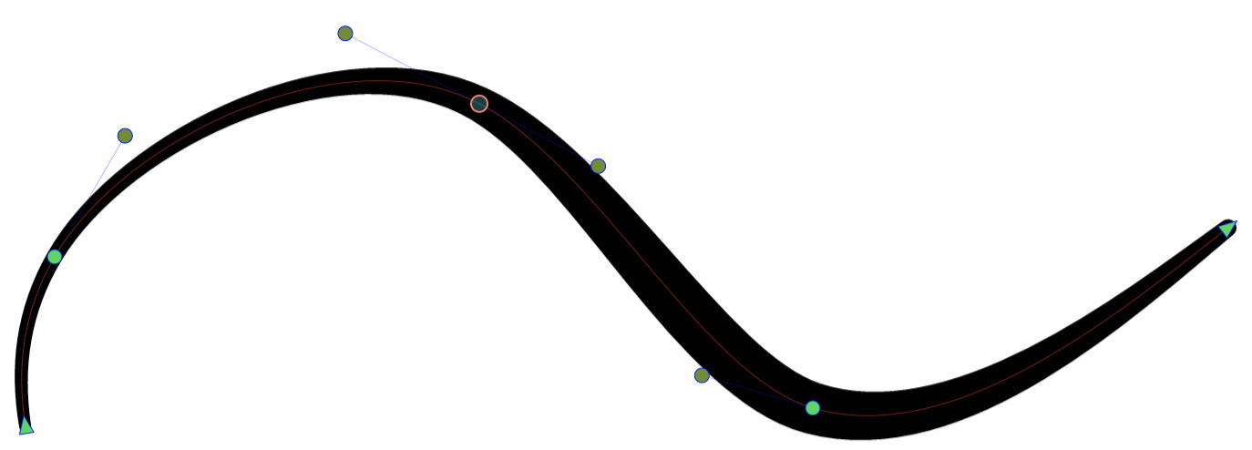
Painting with the pencil tool using pressure.
Pressure Handling
To translate tablet pencil pressure, or mouse velocity to variable width profiles, select a Pressure mode in the context panel. The pressure options are:
- None - Create uniform width strokes.
- Current - Use the current variable width profile, selected in the stroke panel.
- Pressure - Use the tablet pressure input to create variable width profiles.
- Velocity - Use the mouse velocity to create variable width profiles.
- Inverse Velocity - Use the mouse velocity in inverted mode.
Pencil Tool Options
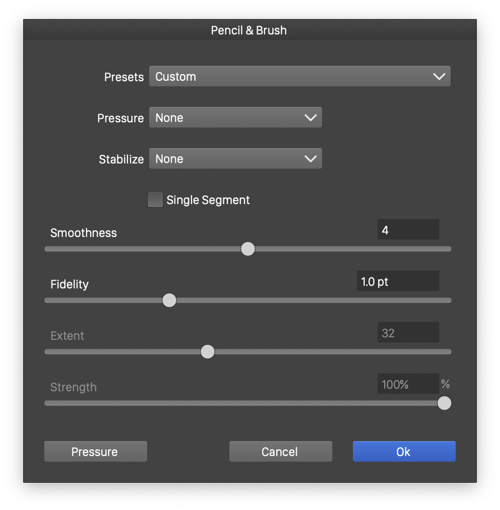
Options of the pencil tool.
The width and calligraphic shape of the resulting outline stroke option can be set before drawing using the tool options view. To open the tool options view, double click on the tool icon. The tool options view will contain the settings available for the width paint brush tool.
- Pressure (slider) - Select the pressure handling mode.
- Stabilize - Select the pen path stabilization scheme used while painting with the brush.
- Smoothness - Set the smoothness of the resulting path. The path is created by approximating the locations traversed by the brush paint using the minimum number of curve segments.
- Fidelity - Set fidelity of the variable width profile. Lower values result in more precise but complex profiles, while higher values will result is less profile nodes.
- Extent - Set the size of the pen stabilization window.
- Strength - Set the strength of the pen stabilization.
- Pressure (button) - Edit velocity pressure mode options. The stylus pressure can be simulated by varying the speed of the mouse while painting with the pressure sensitive tool.