Symmetrigon Shapes
Symmetrigon shapes are made by symmetrically repeating one or more open paths along the sides of a regular polygon. In VectorStyler, symmetrigons can be created using the repetition of one open path, or the alternating repetition of multiple open paths. The paths used in a symmetrigon shape can be directly edited using the node tool, or can originate from presets, styles or objects with the shape role.
The properties of a symmetrigon shape can be edited from the Shape panel. The paths forming the sides of the symmetrigon are editable using the Node tool.

Symmetrigon shapes: (A) a symmetrigon with 5 linear sides: (B) a symmetrigon with 5 curved sides, (C) a symmetrigon with 6 curved sides, (D) a symmetrigon with 3 sides.
Drawing Symmetrigons
Symmetrigons can be drawn using the  Symmetrigon tool from the application toolbox. To draw a symmetrigon:
- Select the
 Symmetrigon tool from the toolbox.
 - Press the mouse on a starting location on the canvas, this will be the center of the symmetrigon.
- Drag the mouse to set the symmetrigon radius and rotation.
- Hold the Shift key to restrict the symmetrigon rotation to user specified increments (45 degrees by default).
- Press the Up arrow key to increase the symmetrigon sides while dragging.
- Press the Down arrow key to decrease the symmetrigon sides while dragging.
- Release the mouse to create a symmetrigon with the selected radius and rotation.
If the document view is rotated, the symmetrigon shape will be drawn with the opposite rotation angle to the view.
The default symmetrigon options can be set by double clicking on the Symmetrigon tool icon in the toolbox. For example: the number of sides of the symmetrigon can be set numerically before drawing the symmetrigon.
To create a symmetrigon by setting the numeric properties of the shape, click at a point on the canvas. This will open the Symmetrigon view (described below) that contains all the symmetrigon shape properties. Set the required values and press Ok to create a new object with a symmetrigon shape.
Editing Symmetrigons
The Node tool can be used to interactively edit the side shapes of a symmetrigon:
- Select the object with a symmetrigon shape.
- Select the
 Node tool from the application toolbox.
 - The nodes of the paths forming the symmetrigon sides are shown.
- Edit the nodes and segments, just like a normal free form path.
- New nodes can be created as described in the Edit Paths section.
- Symmetrigon sides cannot be broken into multiple sub-paths.
The side shape of a symmetrigon can be selected from a list of shape presets, styles or object references with the shape role. This enables the dynamic linking the symmetrigon side to an open shape of an object.
To link the symmetrigon side to an object with an open shape, use the following steps:
- Create or select an object with an open path shape that will be used as a symmetrigon side.
- Edit the object properties using the Object Options command from the Object menu.
- Set a name for the object, and select the Shape role from the menu accessed using the Role button.
- Apply the object properties by pressing Ok.
- Select or create a new symmetrigon shape.
- The shape list in the Shape panel will contain the objects with the Shape role.
- Select the shape from the shape list.
- When the object with the open path shape is modified, the symmetrigon sides are adjusted automatically.
Symmetrigon Properties

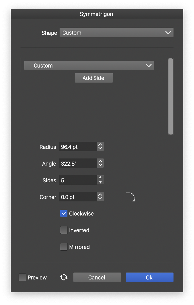
The Symmetrigon view.
The properties of a symmetrigon shape can be edited in the Shape panel when the shape is selected, or in the Symmetrigon view, either from the shape panel, or when editing a shape style.
The following properties can be adjusted for a symmetrigon shape:
- A list of shape preset and style widgets are shown to select the shapes that form the symmetrigon sides. By default, there is one shape (repeated along the sides of the symmetrigon).
- Use the Add Side button to add more shapes. If more than one shape is selected for the symmetrigon sides, the shapes will be picked in the order of appearance and stretched along the symmetrigon side.
- Radius - Select the radius of the symmetrigon.
- Angle - Select the rotation of the symmetrigon.
- Sides - Select the number of sides of the symmetrigon.
- Corner - Select the corner size and select the corner shape.
- Clockwise - Set the star shape direction to clockwise or counter-clockwise. The shape direction can be observed with the Node tool after converting the star to curves.
- Inverted - Select the side shape inversion mode. When checked, the side shape is reversed.
- Mirrored - Select the side shape mirroring mode. In mirrored mode, the side shape is reversed on every second side.
