Editing Paths
The shape of an object (including groups), can be a geometric primitive, a free form path or a composite shape consisting of multiple shapes. This section describes a number of tools used to edit free form paths.
If an object shape is a geometric primitive or a composite shape, use the Convert to Curves command to convert the shape to a free form path. The object shape may also be a vector text shape. The Convert to Curves will convert the text shape into a single object containing a set of paths as its shape. Each glyph of the text is converted into a path. The set of paths can be separated into objects using the Break Apart command.
A free form path may contain multiple sub-paths, each with a starting and ending node. A path may be open or closed. Paths and sub-paths are made of a sequence of segments that can be lines, quadratic or cubic curves. The type of a segment can be changed while editing a path. A node in the path (connection between the segments) can be of Cusp, Smooth or Symmetric type, determining how the tangent control nodes are handled when editing.
In VectorStyler, paths can contain both cubic and quadratic segments (along with line segments). Cubic segments are shaped by two independent control points at each ends. Quadratic segments, typically obtained from TrueType font glyphs, are shaped by a single control point.
The Node Tool
The Node tool is used to edit geometric primitives and free form paths, depending on the selected objects. When a geometric primitive is selected, the function of the Node tool depends on the type of the geometric primitive. The editing of various geometric primitives is described in other sections of this chapter.
When a vector text shape is selected, the Node tool can be used to adjust the baseline shape of the text. Editing the text baseline shape as a free form path can be used to create various text on path effects. For a detailed description on the text on path features, see the Working with Text chapter.
When a free form path is selected, the Node tool can be used to edit the curves and nodes of the path.
Indicators
The path editor uses various indicator types to show the nodes, control points and node selection of a path. The size and color of the node and control point indicators can be customized in the application settings.
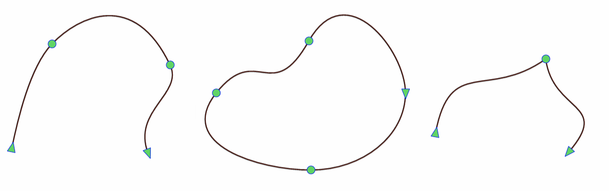
Three free form path shapes with no selections.
When no nodes are selected, the regular node indicators are shown with circles. The start and end nodes are shows as triangles, pointing to the path direction.
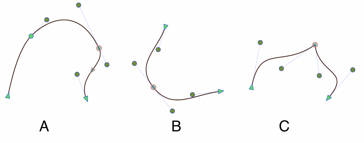
Three examples of path node indicators: (A) a smooth node is selected and an inner location is highlighted indicating the curve direction. (B) a symmetric node is selected (tangent controls are of equal distance from the node). (C) a cusp node is selected.
When a node is selected, its tangent control points are also shown (for curves). When hovering over a line or curve segment, the direction of the path is shown with a triangle indicator. The selected node is shown with a different color (customizable in the application settings). The control point and line colors are also customizable.
Selecting Nodes
Clicking on a node will select the node. Holding the Shift key and clicking on a node will add the node to the selection. Dragging the marquee (box by default) selector will select the nodes inside the marked area. The lasso selection tool can also be used to select multiple nodes inside an irregular area.
A curve segment can be selected at any internal location (not just the ending nodes) and dragged to change the curve. Selecting and dragging an internal location of a line, will change it to a curve.
Node and Segment Types
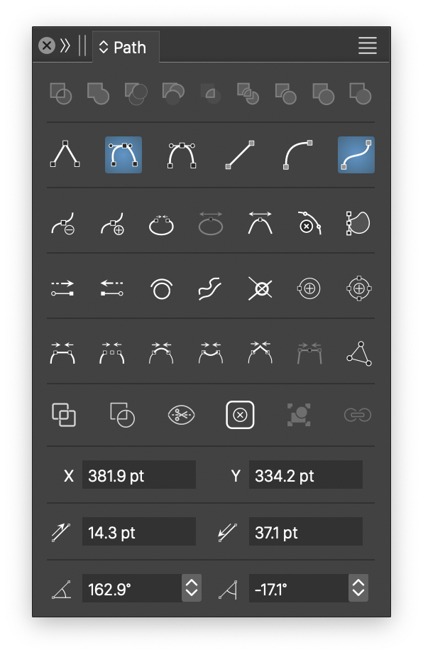
The Path panel.
Each node and segment of a path has a type specifying the mode of operation on that node. The type of the selected nodes and segments can be changed using the Path panel, the Properties panel or the Context tool bar.
The type of a node can be one of the following:
- Cusp - at a cusp node the tangent controls of previous and next curve segments can be independently adjusted. Cusp nodes can be of any angle. Shape corners can be set only at cusp nodes.
- Smooth - at a smooth node, the tangent controls of the two curve segments are along the same line (but not the same distance). This means that the path is smooth at the node, and no shape corner can be set at this node.
- Symmetric - at a symmetric node, the tangent controls are along the same line and distance from the node making the curve smooth at the node and of similar curvature before and after the node. Symmetric nodes cannot have shape corners.
The following segment types can be used in a curve:
- Line - a line segment, with no control points. The starting and ending nodes can be cusp, smooth or symmetric. When the symmetric node type is used at a line segment end, the length of the tangent control will be half of the line.
- Quadratic - a quadratic curve, having a single tangent control point. Quadratic curves are used for example in some of the TrueType and OpenType fonts, and provide an easy control over the curvature of a shape.
- Cubic - a cubic curve, having two independent tangent control points. The tangent controls are used to set the direction of the curve at the start and end nodes. Cubic curves are the most common form of segments used in vector graphics.
Moving Nodes and Curves
The selected nodes can be moved, by holding the mouse over a selected node and dragging. Holding the Shift key will restrict the node movements to horizontal or vertical only (subject to the current view rotation). When moving a tangent control point, holding the Shift key will restrict the angle formed by the line between the control point and the corresponding node on the path.
While moving a single node at the end of a line segment, or moving a control point, holding the Command (Mac) Control (Windows) key will keep the length of the line (or distance of the control point from its node) fixed, and change the angle only. When moving a tangent control point, holding the Command (Mac) or Control (Windows) key will restrict the distance between the control point and the corresponding node on the path.
A line or curve can be selected at any location along the segment. The selection is indicated by a triangle, showing the direction of the path. When selected at an inner location (not at the start or end nodes), a curve segment can be adjusted by moving that location. When moving an inner location of a line, the line is automatically converted to a curve segment.
The control point direction and sizes at a node can be transfered to another node with copy and paste. Select the source node, and use the Copy (Command+C) command. Then select the node to be changed and paste.
Add and Remove Nodes
A new node can be created on any segment by first selecting an inner location along the segment and pressing the Plus key. This will break the segment into two segments, and create a new smooth node at the selected location. If the segment was a line, the node will be a cusp node.
When a node is selected (a start or end of a segment), pressing the Plus key will create a new node at the middle of the next segment (the segment after the selected node). To break multiple segments in the middle, select the nodes at the start of these segments, and press the Plus key.
The selected nodes can be deleted by pressing the Delete key. The selected nodes are removed, and the curvature of the path is adjusted to follow the original path as close as possible, but with less nodes and segments. To avoid approximating the original curvature, and keep the control points before and after the deleted nodes, disable the Adjust Node Removal Curvature option in the application Settings.
When an internal location of a segment is selected, pressing the Delete key will disconnect the path at the two endings of the segment, and will delete the segment.
To remove the segments around the deleted node, and disconnect the path, press the Option+Delete keys.
Path nodes can also be created or deleted using buttons from the Path panel, Properties or Context panels.
Scaling and Rotating Multiple Nodes
To scale or rotate a part of a path, select the nodes using the marquee tool or by clicking while holding the Shift key. Once the nodes are selected, select the Scale or Rotate (Skew is also supported) tools from the toolbox.
When the Scale or Rotate tools are activated, while a set of path nodes are selected, the transform frame is displayed around the selected nodes only. Use the handles for scaling or rotating of the transform frame to adjust the selected nodes. Only the selected nodes and their control points are scaled or rotated, the rest of the path remains unchanged.
Duplicating a path section.
Any continuous section of a path can be extracted and copied into a new object.
To copy a section of a path, select all nodes of that section. Hold the Option(Alt) key and start moving the selected nodes. The selected path section is copied into a separate object.
Stretching a path section.
A section of a path between two selected node can be stretched and rotated using the Node tool. To stretch a section of a path, select a first and a last node and start dragging the node (this will move the two selected nodes). Press the Option(Alt) key to keep the opposite node fixed and move only the dragged node to stretch the curve between the two selected nodes.
While stretching a path section, holding the Control key will fix the angle between the starting and ending nodes allowing to change the length of the section, while holding the Shift key will fix the length of the stretched section and will allow to change the rotation of the section around the opposite node.
Trimming Self-Intersecting Points
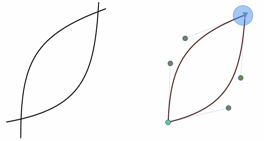
Trimming self-intersecting points of a path with two clicks.
When drawing and merging multiple free form paths, it is quite common that separately drawn path ends don’t exactly match. Connecting the ends of such paths is possible using the Path panel, but it will result in undesirable movement of the control points and the curvature may change. Such scenarios occur especially when creating hand drawn line art, or manually tracing artwork.
The example captured in the figure, shows a path consisting of two sub-paths drawn by hand using the pencil tool. The paths were combined using the Combine command of the object menu. The problem here is that the start and end of these paths don’t exactly align to allow a proper joining into a single filled path.
The Node tool can be used to quickly cleanup such path intersections using only a single click. Select the path object to be edited, and select the Node tool. Hold the Option (Mac) or Alt (Windows) key (without selecting any node), a larger (blue) circle will show. The circle indicates the area where self-intersecting points are cleaned (other parts of the path remain unchanged). Move the mouse over the self-intersecting point to be cleaned (the circle marquee center should be close to the point), while still holding the Option (Mac) or Alt (Windows) key. Click with the mouse over the self-intersecting point, and if the two short edges are correctly identified (i.e. they are not too long), a new node is created at the self-intersecting point, the short edges are removed and the path is joined at the new node.
The Simplify Tool
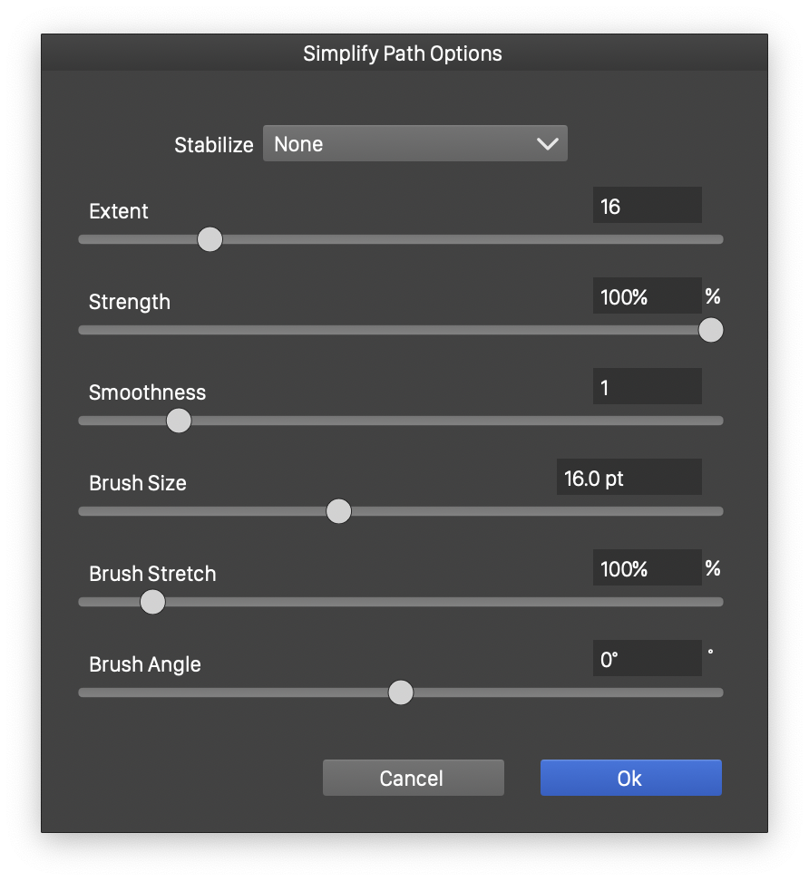
The simplify path tool options.
The  Path Simplify tool can be used to simplify a selected part of a path, by removing nodes and smoothing the curvature of the path. Paths created in automatic image tracing, or when importing artwork from other file formats, may have too many nodes and are not easily editable. By simplifying such paths, curves can be smoothed and nodes removed to obtain an editable path.
The smoothness amount used by the Simplify tool can be set in the Properties panel or in the Context tool bar.
Select a path to be simplified and select the Simplify Tool from the application toolbox. The existing nodes of the path are shown using the current node indicator style (customizable in the application settings). Press the mouse (or tablet pencil) with the simplify tool at a location on the path and drag along the path to cover the part that should be simplified. Release the mouse and the painted path region is simplified using the current smoothness amount.
The Simplify Path tool options can be set by double clicking on the tool icon. The following options are available:
- Smoothness - set the smoothness of the resulting path. Larger values result in more removed nodes.
- Stabilize - Select the path stabilization method.
- Extent - Select the length of the path stabilization window.
- Brush Size - Set the size of the brush used to cover the nodes.
- Brush Stretch - Set the stretching of the brush tip shape.
- Brush Angle - Set the rotation of the brush tip shape.
Redraw Parts of a Path
The  Pencil tool can be used to redraw part of a path. Select the object with the path shape. Select the Pencil tool and position the cursor at a location on the path, where the redrawing should start (sufficiently close to the path). Press the mouse (or tablet pencil) and paint the new path. Release the mouse at the location of the original path, where the redrawn part should end.
The part of the path between the starting and ending locations of the path is replaced with the newly drawn path.
Erase Parts of a Shape
Parts of a closed or open shape can be erased using the  Eraser tool. Select the object with the shape that must be modified. Select the Eraser tool and start painting over the path. The regions of the path painted over with the current brush size and nib shape will be erased.
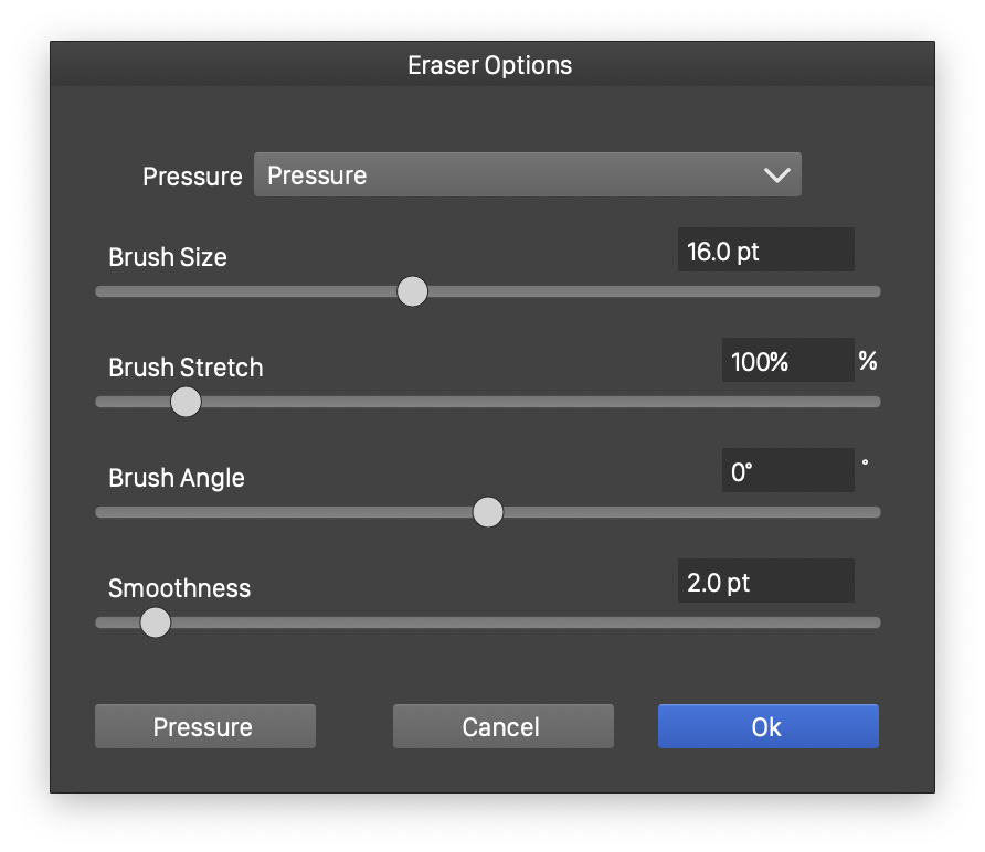
The Eraser tool options.
The erasing of shape regions uses the boolean shape operations to remove from the shape. The resulting path node set is simplified using the current smoothness value. If the selected shape was a geometric primitive or a vector text, it will be converted to curves, at the moment the eraser tool cuts into the shape.
If an open path is selected, the eraser tool can be used to remove parts of the path. If multiple objects are selected, the eraser tool will erase from all of the selected objects that are painted over.
The size of the brush and the nib shape used by the eraser tool can be set in the tool options view. To open the tool options view, double click the eraser tool.
The Brush Size field contains the size of the eraser brush. The Brush Stretch and Brush Angle fields edit the stretch and angle of a calligraphic brush nib shape.
The Pressure drop down contains various pressure modes that can be used to paint a variable width erasure area. The Pressure button opens the pressure options used when the Velocity pressure mode is selected.
The Shape drop down contains shape presets and styles that are used when clicking with the eraser tool. Check the Shape in Box to use the selected shape when erasing with a region.
To erase a region from the shape, hold Option(Alt) and drag the mouse. By default, the erased region will be rectangular. Use the Shape in Box and Shape fields in the context panel to select other shapes for region erasing.
Erasing between intersections
The erase tool can also be used to erase parts of paths between intersection points. This is similar to the erasing in dynamic mode of the pencil tool. By holding the Shift key and painting over the sections of a path, located between intersection points, these sections can be erased.
To erase sections of a path, with the erase tool:
- Select the objects to be used in erasing. The selected objects determine the intersection points.
- Select the Eraser tool.
- First hold the Shift key, and then press the mouse to paint over the sections of a path to be erased.
- When the mouse is released, the marked sections located between intersection points are erased.
- The intersection points are determined using the originally selected objects.
When erasing parts of paths, the remaining parts are automatically reconnected, if their endings match and they were modified by erasing. This can also result in closed shapes, when multiple outer parts of intersecting open shapes are erased.
The automatic path merging mode can be selected from the Join drop down in the context panel.
The Trim and Join Tool
The  Trim and Join tool is used to cut and join shapes at intersecting locations. The trim and join tool typically works on multiple shapes.
To modify shapes with the trim and join tool, select the objects and select the trim and join tool. Paint over the sections of shapes that should be removed. The paint is indicated with a thin red line, and the sections intersecting the line will be removed.
An open path can be closed by extending at either or both ends along the curvature, by circling over the two ending points while dragging the mouse. If the path does not self intersect along the curvature, and the Option(Alt) key is not held, the path will be removed if it has no intersections.
The sections are defined by parts of curves between two intersection points. Once the paint is released, the sections painted over by the mouse are removed (cut out), and if possible, the shapes are joined at the intersection points.
To remove a single section (without painting a marker), hover over the path section with the mouse, and click when the section is indicated with a red line.
The trim and join tool can also be used to extend an open path until it hits an other selected path. To do this, hold Option(Alt) and paint over one of the path endings. If there are paths in the way along the curvature of the painted over path, the path is extended until it intersects an other path (or itself). The path extension is done along the curvature of the last (or first) segment of the path.
The stroke width profiles of trimmed paths can be cut at the trimming location, by enabling the Profiles option in the context panel.
The trim and join tool options can be set in the context panel:
- Source - Sets the source of shapes to be considered by the trim and join tool. This can be:
- Selection - Only the previously selected shapes are adjusted.
- Layer - All shapes on the current layer are considered for adjustment.
- Canvas - All shapes on the current canvas (all layers) are considered for adjustment.
- Join - Sets the joining mode of the shapes when a section is removed. This can be:
- None - There is no attempt to join shapes.
- Same Style - Joining occurs only when the shapes have the same style.
- Same Layer - Joining occurs only when the shapes are on the same layer.
- Always - Always join shapes.
- Profiles - Check to adjust the stroke width profiles of the trimmed and joined shapes.
- Guidelines - Enable or disable the use of guidelines to create intersection points and shape sections.
The Extract Path Tool
The  Extract Path tool can be used to extract sections of paths between two intersection points. The tool works in a similar way as the Trim and Join tool, with similar options available in the context panel.
To extract shapes with the Extract Path tool, click+drag over the section of a path subject to the selection options. The path section between the two nearest intersection points is extracted and a new object is created with the path.
Path sections between intersection points with Guidelines can also be extracted, by enabling the option in the context panel.
The following options are available in thre context panel:
- The Source option has the similar role as in the Trim and Join tool.
- Remove - Check to remove the extracted path section from the original path.
- Profiles - Check to adjust the stroke width profiles of the extracted shapes.
- Guidelines - Enable or disable the use of guidelines to create intersection points and shape sections.
The Knife Tool
The  Knife tool can be used to cut open or closed shapes into multiple pieces. To modify a shape (or shapes) with the knife tool, select the objects with the shape and select the knife tool. Paint the region of the path to be separated, with the knife tool. Typically, the painting starts and ends outside of the path, traversing the region of the path where the cutting occurs.
The result will be an object using the same fill and outline style of the original object, but containing multiple sub-paths. Use the Break Apart command to separate the object into multiple path objects.
When the Knife tool is active, the contact panel contains a tool specific option Snapping that can be used to enable snapping while painting with the Knife tool. When the knife snapping is enabled, and a snapping mode is also enabled in the snapping panel, the Knife tool will snap to the closest guidelines or other snapping targets.
The Scissor Tool
The  Scissor tool can be used to break shapes at selected locations along the outline.
To modify a shape with the scissor tool, select the tool and hover over the shape outline. The active shape is indicated by showing its nodes. Click along the outline at the desired location, to break the shape into open paths at that location.
The resulting shape can be separated into open paths using the Break Apart command of the Object menu.
The Extend Path tool
The Extend Path tool can be used to extend or reduce an open path along its curvature. The Extend Path tool is activated using the  icon in the toolbox (grouped with the path tools).
The path can be reduced along its current shape, while the extension can be done by extending along the curvature or along a previously saved shape preset. The Extend Path tool can also shift the position of existing nodes along the curve shape, keeping the original curve as much as possible.
The following steps are used to adjust an open path with the extend path tool:
- Click on the path that is to be adjusted, to make it the active (selected) path.
- The path start end ending locations are marked with a knob perpendicular to the path.
- The nodes of the path are indicated with circular knobs.
- Drag a node along the path to adjust its positions.
- Drag the starting or ending knobs outward of the path to extend the path along its curvature.
- Drag the starting or ending knobs inward along the path to reduce the path along its curvature.
- Use the Pick Shape button in the context panel can be used to pick the currently selected shape as a path extension profile.
- Use the Extend Mode drop down contains a list of predefined and user created path extension profiles. The predefined profiles are Curve for curvature, Line to extend along a line, and Arc to extend along an open arc.
The Offset Path tool
The Offset Path tool can be used to create local offset adjustments of paths in a destructive editing mode. The local offset path will use a variable offset profile, adjusted by the user when editing the path. The Offset Path tool is activated using the  icon in the toolbox (grouped with the path tools).
The Offset Path tool can also use a custom shape overlay, to replace part of a shape. The options of the Offset Path tool can be selected from the context panel.
The following steps are used to create local variable offsets with the Offset Path tool:
- Click on a path that is to be adjusted, to make it the active (selected) path.
- The offsetting start and ending locations are shown with a red knob perpendicular to the path.
- The part of the path that will be adjusted is shown with a red highlight.
- Drag the starting and ending knobs to select a part of the path for adjustments. This can be changed later.
- Drag from the inside of the selected area outwards, the path will be offset according to the cursor movement.
- The offset distances are shown with blue knobs, similar to the stroke width tool.
- Drag the blue knobs to set the offset distance, and create new distance knobs by dragging from a location between the starting and ending positions.
- The modified shape will be shown with the current object style, while the original path section is shown with a red highlight.
The Offset Path tool options are available in the context panel:
- The width profile used to offset the shape can be changed from the Stroke Width panel, or the context panel.
- The Join drop down contains the corner joining type options for the path offsetting.
- The Overlay drop down contains shape styles and presets that can be used to overlay on the edited path section instead of offsetting.
- Use the Repeat field to set the number of repetitions for the overlay shape.
The Reshape tool
The Reshape tool can be used stretch sections of a path in different directions. The Reshape tool is activated using the  icon in the toolbox (grouped with the path tools).
The Reshape tool will move the selected nodes and control points of a path, proportionally to the distance of mouse drag starting location to these points. The reshape tool will not add new nodes and will not convert lines to curves.
The reshape tool can be used to make small adjustments to sections of a shape that smoothly merge into the original shape.
The following steps are used to adjust a path with the Reshape tool:
- Select the object before activating the reshape tool.
- Alternatively, the reshape tool can also select nodes, by holding the Shift+ key.
- If no object is selected (or the Escape key is pressed to deselect), the reshape tool can select an object with a simple click.
- Select one or more consecutive nodes along the adjusted path.
- Drag the mouse from a location on the canvas (does not need to be on the path).
- The selected nodes are adjusted based on their proximity to the starting location.
The Path Eraser tool
The Path Eraser tool can be used erase sections of a path. The Path Eraser tool is activated using the  icon in the toolbox (grouped with the path tools).
When erasing sections of a path, the segments between the erased nodes are removed and path is opened.
The following steps are used to erase segments of a path with the Erase Path tool:
- Select the object before activating the erase path tool.
- Alternatively, the erase path tool can also select nodes, by holding the Shift+ key.
- Paint with the eraser tool along the path, from the starting to the ending location of the part to be erased.
- Release the mouse will erase the painted section of the path.
Reversing the Path Direction
The Reverse Path Direction command reverses the direction of paths. This command is available when the selected object shape is a path of curve and line segments. The path direction may determine the filled area if the winding fill rule is used. The Reverse Path Direction command also works with the Node tool, when the reversing is restricted to the selected sub-path of the edited path.
Converting to Curves
The Convert to Curves and Convert Shapes to Curves commands convert the selected parametric shapes to curves.
In VectorStyler, drawing a rectangle, ellipse, polygon, star or other shapes will result in a parametric shape. This shape can be edited by editing its parameters, either interactively (with the Node tool) or from the Shape panel. The internal curves and lines making up the parametric shape are not immediately available for editing.
To convert a parametric shape to a path (sequence of curves and lines) use Convert to Curves command. The resulting shape will be a freely editable path consisting of curves and lines. If corners were used in the shape, the Convert to Curves command will also convert these corners to curves and lines.
To keep the corner attributes and shape effects editable, use the Convert Shapes to Curves command. In this case the parametric shape is converted to curves, but the corner attributes are kept and remain editable using the Corner or Node tools.
Some design processes may require flattened lines to exported. The curves of the selected object can be converted to (flattened) lines using the Object -> Shape -> Convert to Lines command. The number of lines created for a curve can be controlled with the current zoom level.
When a shape contains flat curves with alignment control points making them lines, the Object -> Shape -> Flat Curves to Lines command can be used to automatically convert these to lines.
If a shape has a dashed stroke attribute, the shape can be broken into pieces defined by the dash using the Object -> Shape -> Convert to Dashes command.
Add Path Nodes
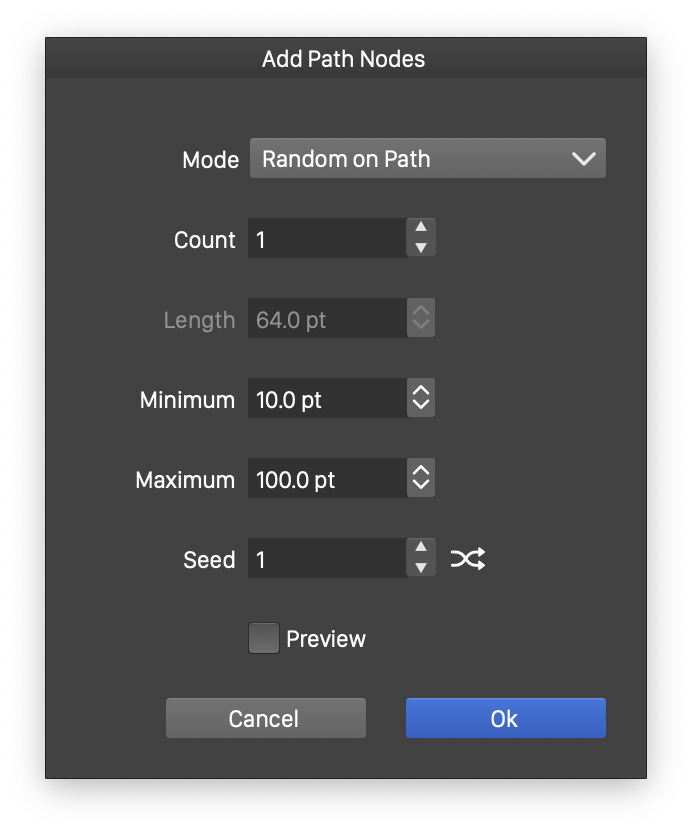
Adding multiple nodes
The Object -> Shape -> Add Path Nodes command can be used to add multiple nodes to a path at various locations, in one step. The following options are used:
- Mode - Select the node insertion mode:
- Fixed on Segment - Add a fixed number of nodes set in the Count field, to each segment.
- Longest Segment - Add Count number of nodes to a path splitting the longest segments.
- Segment Length - Add nodes by splitting segments longer than Length.
- Random Length - Add nodes by splitting segments into random lengths.
- Random on Segment - Add Count number of nodes to each segment, at a random locations.
- Random on Path - Add Count number of nodes to the path, at a random locations.
- Random on Extrema Points - Add nodes at the extrema points of the path.
- Count - Set the number of nodes to be added for a segment or the whole path.
- Length - Set the length of the segments to break.
- Minimum - Set the minimum length of a segments
- Maximum - Set the maximum length of a segments
- Seed - Randomization seed value.
Simplifying Paths
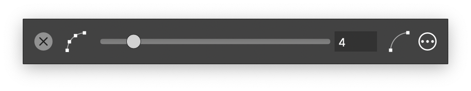
The basic mode of the *Simplify Path* view.
The Simplify Path command is used to remove nodes from the selected path by further smoothing out curves. The Simplify Path command opens a view containing the smoothness slider and other options. This view is persistent and will remain open to allow other objects to be selected and adjusted.
- The smoothness of the new path following the original path can be set using the slider .
- Higher values mean a larger difference and less nodes of the simplified path from the original path.
- Smaller values of Smoothness result in a simplified path that is closer to the original path, but less nodes are removed.
- Additional options can be accessed by clicking the
 button.
 - Stabilize - select the path stabilization mode.
- Extent - set the length of the stabilization window over the path.
- Strength - set the strength of the stabilization.
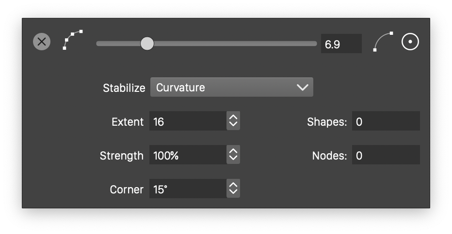
The detailed mode of the *Simplify Path* view.
Connecting Paths
A collection of separate open paths can be merged into fewer and longer shapes using the Object -> Shape -> Connect Overlapping Nodes command.
The current zoom level is used as a “parameter” of the node proximity tolerance. Zooming out will make it more likely that two close nodes are merged.
To do this select the shapes that are to be merged. Make sure that the endings of these shapes are sufficiently close at the locations where there should be connected. Unce the shapes a re selected, select the Object -> Shape -> Connect Overlapping Nodes command.
Removing the Shape
The Clear Object Shape command removes the shape from the selected object. This command is available only if the selected object contains a content that allows the removal of the shape. The typical use of this command is to remove the (clipping) shape from a group object.