Image Tracing
Images consisting of pixels (PSD, PNG, JPEG), imported into a VectorStyler document, can be converted into vector objects using the Image Trace panel. Image tracing can be used to create vector shapes, filled or outlined with solid color, as a basis for an artwork.
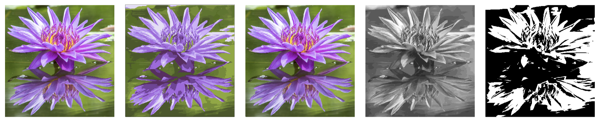
An image (first) converted into vectors using various options.
The image to vector conversion can be customized using a large number of options. Various default options for typical use cases are available as presets.
The selected image can be converted to vector objects using Image Trace panel, from the Window menu. The Image Trace panel provides access to the image tracing presets and styles, and a set of basic tracing options. Additional options can be accessed using the More Options command of the panel menu.
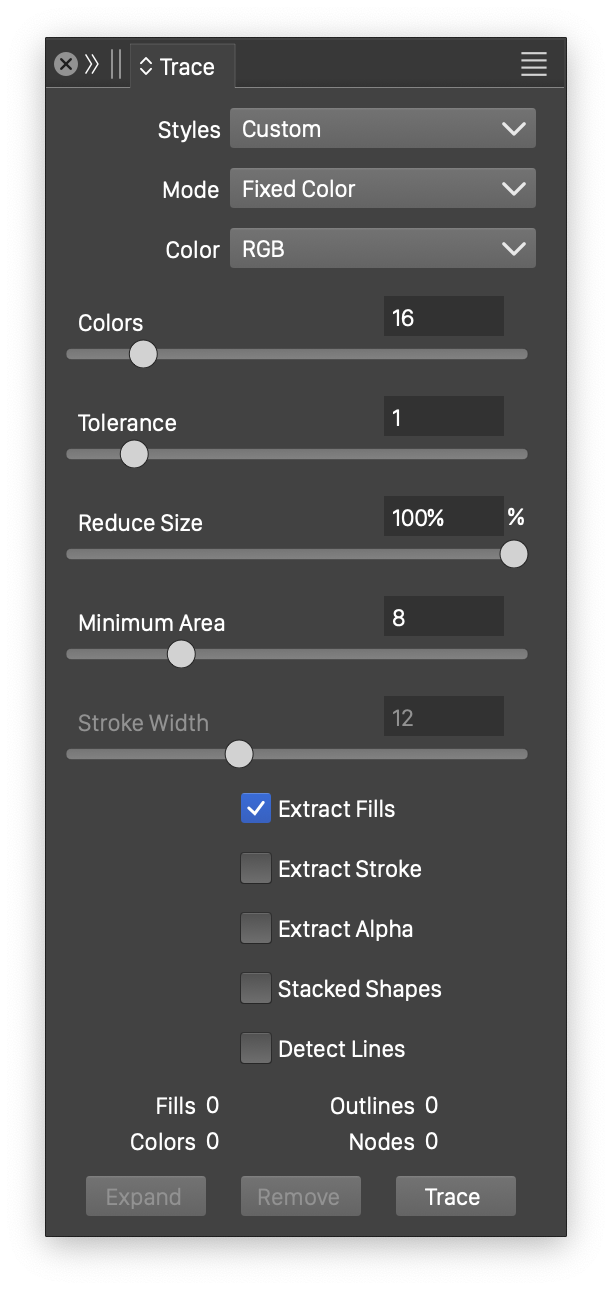
The Image Trace panel.
To convert an image to vector objects:
- Open the Image Trace panel from the Window menu.
- Select the image object to be converted to vectors.
- Select the tracing preset or style from the Styles field of the panel.
- Select other options of the tracing if necessary.
- Click on the Trace button. The image to vector conversion progress is indicated in a view.
- Information about the resulting vectors is shown in the panel, as the number of Fills, Colors, Outlines and path Nodes.
The vectors resulting from the conversion are not immediately available for editing.
- By default, the image trace results in a trace group associated with the image.
- The image trace group settings can be modified from the Image Trace panel, by setting new options and pressing the Trace button.
- The original image can be restored from a trace group by clicking the Release button.
- The trace group can be expanded into a group of vectors, using the Expand Content command from the Styles menu.
- To directly obtain an editable vector group from image tracing, disable the Keep with Image option from the panel menu.
The easiest way to create an image trace is to use an existing preset or style, from the Styles field in the panel. The following presets are available, by default:
- Color Drawing - Used for images of hand drawings with colors, converted into filled shapes.
- Color Outlines - Used for images containing strokes of hand drawings with colors, converted into outlined shapes.
- Gray Sketch - Converts monotone gray sketches to outline strokes.
- Gray Tones - Converts monotone gray sketches to filled shapes.
- High Color Cartoons - Cartoons and images with flat regions, containing large number of colors.
- High Color Shapes - Geometric shapes, with overlaps and large number of colors.
- Low Color Cartoons - Cartoons and images with flat regions, containing only a few colors.
- Low Color Shapes - Geometric shapes, with overlaps and only a few colors.
- Pencil Drawing - Black and white pencil drawing converted to outline strokes.
- Photographic - Smooth transitions, with large number of colors, typical to photographs.
- Thin Outlines - Thin outlines, technical drawings, converted to outline strokes.
The Image Trace panel contains the following basic tracing options:
- Mode - Contains a list of color conversion modes, including color palettes. This can be:
- Black and White - Traces the image to black and white shapes, using the selected Threshold to split the black and white intensities.
- Grayscale - Traces the image to a number of gray scale levels, set in the Levels field.
- Selected Colors - Pick colors from the image to restrict the tracing result to these colors.
- Fixed Color - Traces the image to a fixed number of colors, extracting the most common colors of the image.
- Full Color - Traces the image to a large number of colors, set as the percentage of the total number of Tones.
- Palette Name - Select an available color palette name, to restrict the colors to a color palette.
- Tolerance - Set the curve fitting tolerance in pixels. Smaller tolerance values result in more detailed shapes. Larger tolerance values result in smoother curves, with less detail.
- Reduce Size - Set the amount of image downscaling, before tracing. Image downscaling can be used to reduce the amount of shapes and colors extracted during the tracing process.
- Minimum Area - Set the minimum region size in pixels. Regions of smaller size are merged with their neighborhood. The region size can be used to remove noise and unwanted small spots from the image.
- Stroke Width - Set the maximum stroke width, used when detecting and extracting outline strokes. This option is available if the Extract Stroke check box is checked.
- Extract Fills - Enable or disable extracting filled regions. When disabled, the Extract Stroke option should be enabled.
- Extract Stroke - Enable or disable extracting outline strokes.
- Extract Alpha - Enable or disable the use of the alpha channel of the image, to extract opacity values for filled and outlined shapes.
- Stacked Shapes - Enable or disable the separation of stacked shapes.
- Detect Lines - Enable or disable the detection of straight lines in geometric drawings.
- Trace - Convert the selected image to vector shapes using the current options.
- Release - Release the image tracing group and restore the original image.
Selected Colors
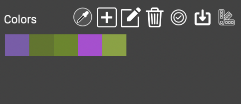
Selecting trace colors.
The colors used in image tracing to vectors can be reduced to a selected set of colors using the Selected Colors tracing mode. The colors can be picked anywhere from the document, the traced image, selected by the user, or added from a color palette. When the Selected Colors tracing mode is enabled, the color picking tools and a color list is shown below the Color drop down.
The colors can be picked from the canvas using the color picker
tool of the Trace panel. When the color picker tool is activated, clicking on a canvas location picks the color from that location and adds it to the list of colors. The color picker tool remains active to pick additional colors, to deactivate click the color picker icon again in the Trace panel, or press the Esc key.
- - Activates the color picker mode.
 - Add a new color to the tracing colors, the color is specified using the modal color selector view.
 - Edit the selected color.
 - Remove the selected colors.
 - Enable or disable the use of the selected colors in tracing.
 - Save the color set as a palette preset for reuse.
 - Select a previously saved palette preset to be used as tracing colors.
Panel Menu
The Image Trace panel menu contains the following tracing options:
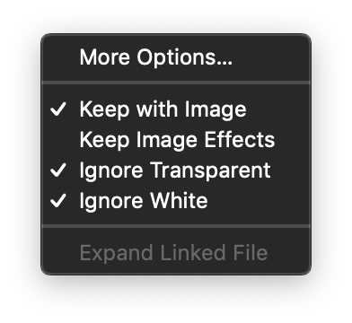
The Image Trace panel menu.
- More Options - Opens the image tracing options editor view, containing detailed settings for image tracing.
- Keep with Image - Tracing creates an image tracing group associated with the image object. When enabled, the vectors are editable only after expanding with the Expand Content command. Image tracing groups can be released back to the original image, using the Release button of the panel. When disabled, the image tracing results in a group of vector shapes, removing the original image. In this case the Undo command can be used to restore the image.
- Keep Image Effects - Traces the original image, before the application of the image effects stacked on the object. The image effects are kept and applied on the resulting vectors.
- Ignore Transparent - When enabled, the transparent regions of the image will result in empty regions with no shapes.
- Ignore White - When enabled, the white regions of the image will result in empty regions with no shapes.
More Options
The Image Trace view, accessed with the More Options command of the panel, contains detailed options used to fine tune image to vector conversions. These may result in new tracing configurations, that can be saved as presets or styles, using the Styles field.
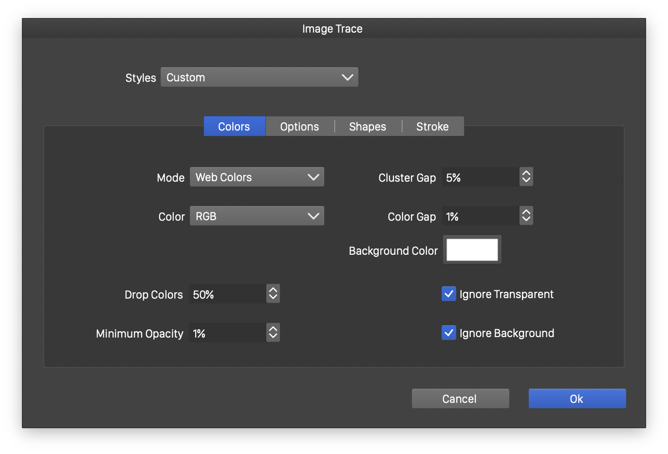
The Colors section of the image tracing view.
- Styles - Select an image tracing preset or style, or create new presets or styles.
- Mode - Select the color conversion mode. This can be:
- Black and White - Traces the image to black and white shapes, using the selected Threshold to split the black and white intensities.
- Grayscale - Traces the image to a number of gray scale levels, set in the Levels field.
- Fixed Color - Traces the image to a fixed number of colors, extracting the most common colors of the image.
- Full Color - Traces the image to a large number of colors, set as the percentage of the total number of Tones.
- Palette Name - Select an available color palette name, to restrict the colors to a color palette.
- Color - Select the color mode used in detecting and extracting colors from the image. Different color modes result in different color similarities.
- Threshold - Set the threshold for the Black and White tracing mode.
- Levels - Set the number of gray levels for the Grayscale tracing mode.
- Colors - Set the maximum number of colors for the Fixed Color tracing mode.
- Tones - Set the relative amount of color tones for the Full Tone tracing mode.
- Drop Colors - Discard the least frequent colors below the selected limit.
- Minimum Opacity - Set the opacity limit for fully transparent shapes.
- Cluster Gap - Set the similarity level of neighboring color regions.
- Color Gap - Set the color difference precision, used to separate background regions.
- Ignore Transparent - Enable or disable the discarding of transparent shapes.
- Ignore Background - Enable or disable the discarding of regions filled with the background color.
- Background Color - Select the background color.

The Options section of the image tracing view.
- Reduce Size - Set the amount of image downscaling, before tracing. Image downscaling can be used to reduce the amount of shapes and colors extracted during the tracing process.
- Limit Size - Set the maximum number of pixels, in millions of pixels. Larger images are downscaled to reduce the detail.
- Window - Set a curve smoothing window in image pixels.
- Smoothness - Set a curve smoothing strength.
- Preprocessing - Setup and edit image preprocessing effects to be used before tracing.
- Extract Fills - Enable or disable extracting filled regions. When disabled, the Extract Stroke option should be enabled.
- Extract Alpha - Enable or disable the use of the alpha channel of the image, to extract opacity values for filled and outlined shapes.
- Linked Image Trace - Enable or disable the creation of image tracing groups.
When Linked Image Trace is enabled, tracing creates an image tracing group associated with the image object. The vectors are editable only after expanding with the Expand Content command. Image tracing groups can be released back to the original image, using the Release button of the panel. When disabled, the image tracing results in a group of vector shapes, removing the original image. In this case the Undo command can be used to restore the image.
- Smooth Downscaling - Check to use smooth downscaling when the traced image size is reduced.
- Keep Image Effects - Traces the original image, before the application of the image effects stacked on the object. The image effects are kept and applied on the resulting vectors.
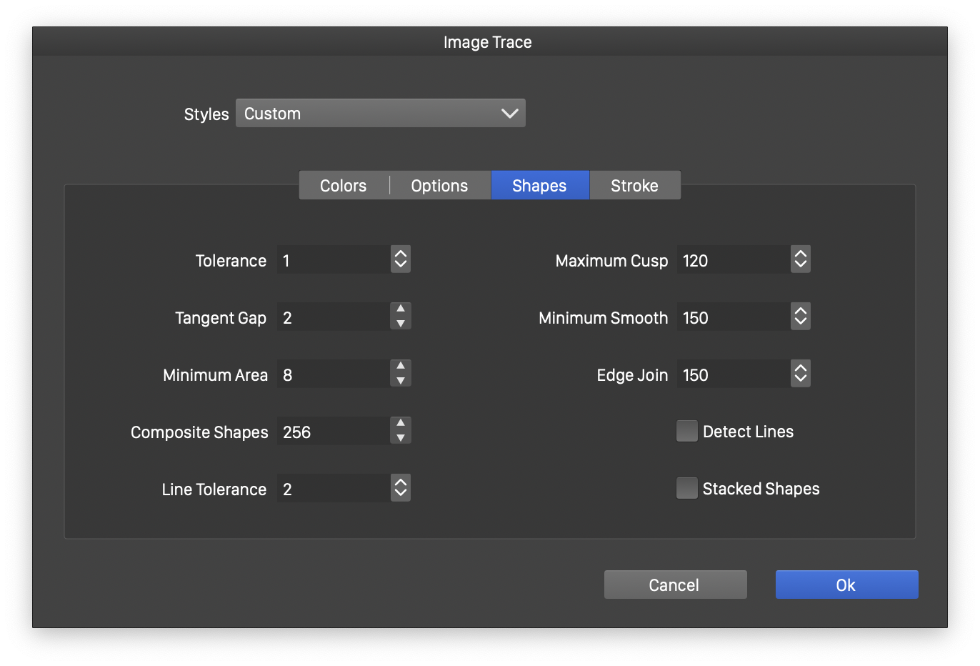
The Shapes section of the image tracing view.
- Tolerance - Set the curve fitting tolerance in pixels. Smaller tolerance values result in more detailed shapes. Larger tolerance values result in smoother curves, with less detail.
- Tangent Gap - Minimum number of pixels required to detect the direction along a path.
- Minimum Area - Set the minimum region size in pixels. Regions of smaller size are merged with their neighborhood. The region size can be used to remove noise and unwanted small spots from the image.
- Composite Shapes - Limit the number of sub paths in composite shapes.
- Line Tolerance - Set the tolerance used to detect straight lines.
- Maximum Cusp - Set maximum angle limiting the creation of cusp (sharp) corners.
- Minimum Smooth - Set minimum angle for smooth corners.
- Edge Join - Set the lower limit of smooth angles when joining edges at object corners.
- Detect Lines - Enable or disable the detection of straight lines in geometric drawings.
- Stacked Shapes - Enable or disable the separation of stacked shapes.
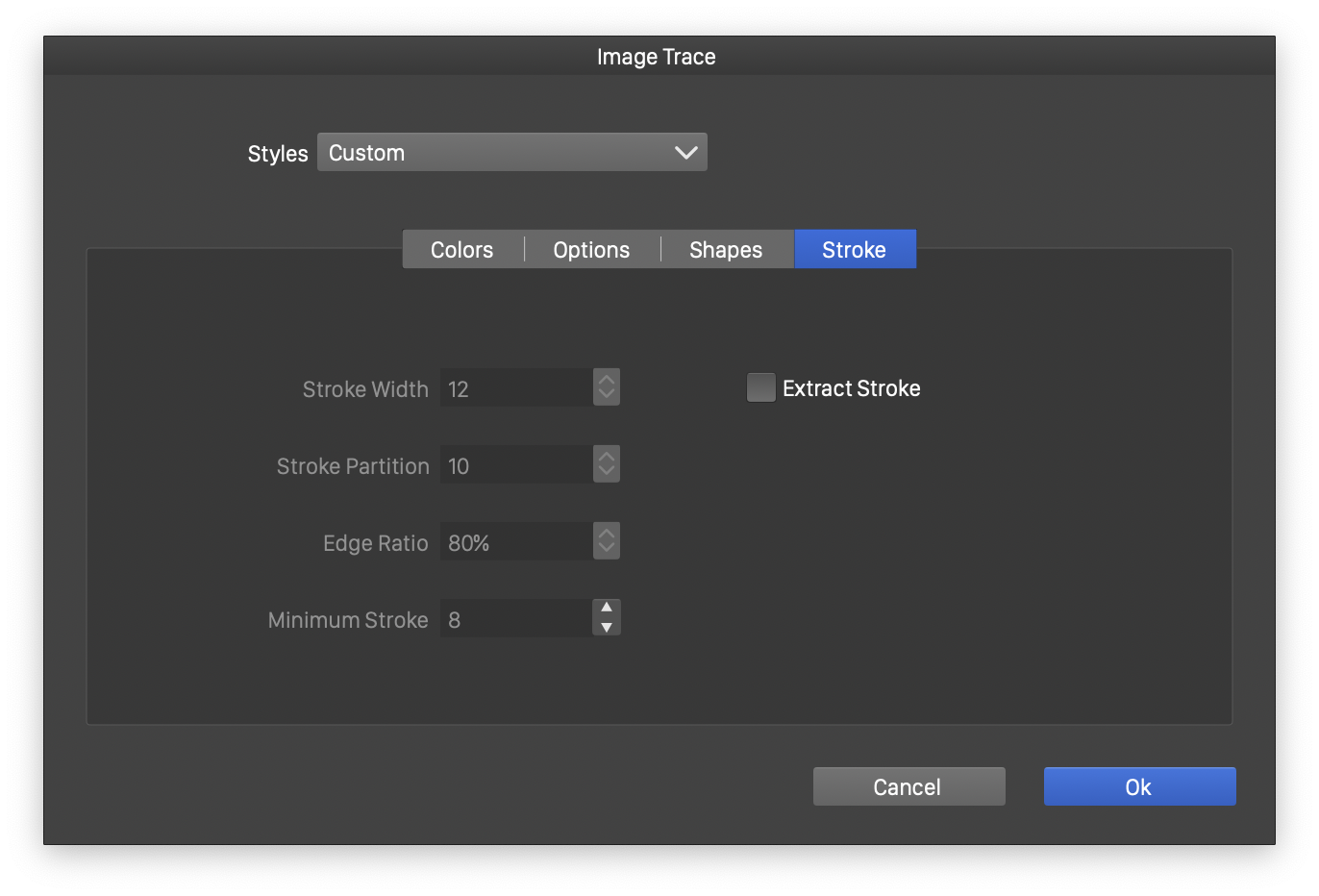
The Stroke section of the image tracing view.
- Extract Stroke - Enable or disable extracting outline strokes.
- Stroke Width - Set the maximum width of a detected stroke.
- Stroke Partition - Extent of an uniform partition used to detect strokes, relative to the partition size.
- Edge Ratio - Ratio of pixels on a stroke edge that have been paired with the opposite side of the stroke.
- Minimum Stroke - Set the lower limit to the size of a region that is detected as a stroke.