Distortion Effects
The Distortion section of the shape effects, contains a set of parametric distortion effects. These effects add some form of distortions to the object shapes, using attributes to set the amount and other aspects of the distortion.
For most of these distortion effects, the interactive shape effect editor can be used to adjust the common attributes visually in the canvas, selected with the primary  shape effect tool.
Some of the distortion effects contain a shape attribute, controlling the shape of the distortion. The shape attribute can be edited using the secondary  shape effect tool. The shape attribute can also be selected from existing shape presets, style or object references with the Shape role.
Circular Bump
The Circular Bump distortion effect stretches the shapes in a concentric direction around a distortion center, inwards or outwards, depending on the Amount of distortion.
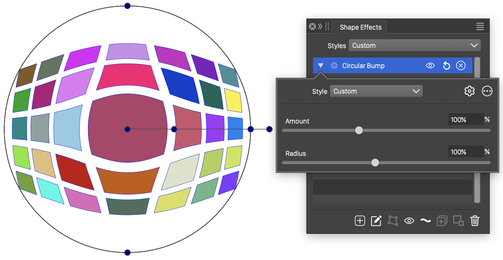
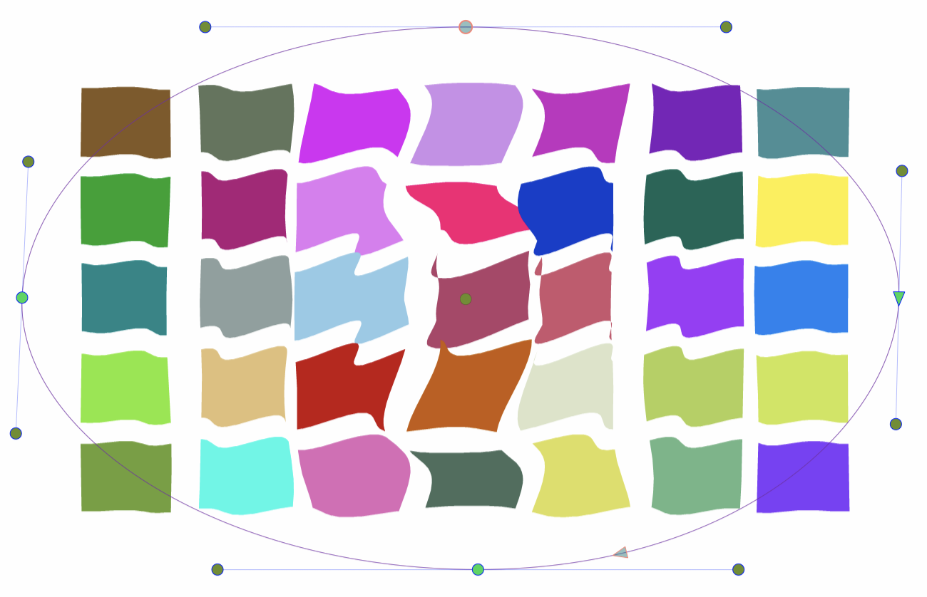
The Circular Bump distortion, with basic options.
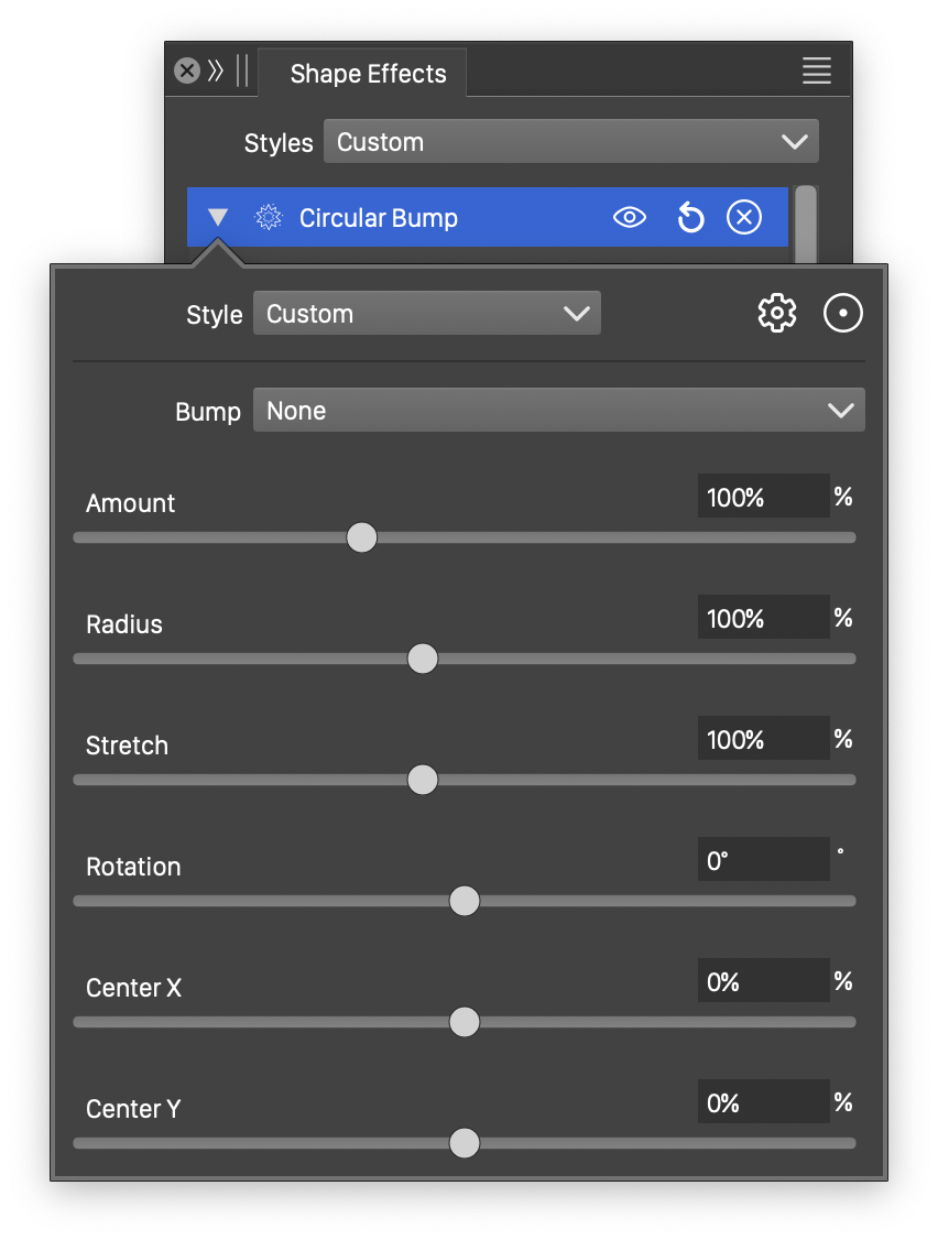
Detailed options of the Circular Bump distortion.
The Circular Bump distortion effect uses the following basic options:
- Amount - Set the amount of bump distortion. For values larger than 0%, the distortion stretches the shapes outwards from the center. For values smaller than 0%, the distortion stretches the shapes inwards to the center.
- Radius - Set the radius of the distorted area. The distortion affects shapes inside this radius around the center.
More detailed options of the Circular Bump distortion are available, by clicking on the  button.
- Bump - Select a function for the bump stretching transition. The Cubic and Monotone Cubic functions are edited by selecting the Edit Curve command.
- Stretch - Stretch the distortion circle vertically, creating an elliptical distortion region.
- Rotation - Set the rotation of the distortion ellipse. The rotation is useful only when stretching is used. Rotating the elliptical region will result in different distortions, while rotating the circular region will create the same distortion.
- Center X and Center Y - Set the center of the distortion circle or ellipse, relative to the object frame. The center can also be adjusted visually using the primary shape effect editor tool.
The button from the Shape Effects panel, activates the shape effect tool used to interactively edit the circular bump distortion attributes.
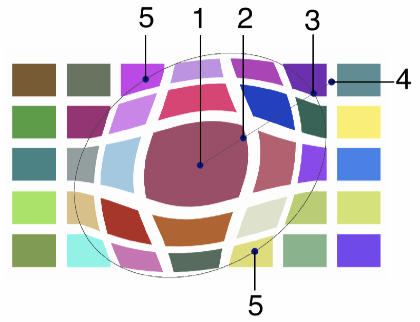
Interactive editing of the Circular Bump distortion.
Interactive editing of the circular bump distortion is done by dragging the handles to change an attribute value:
- (1) - Set the center of the distortion region.
- (2) - Set the amount of distortion, by dragging this handle along the axis of the distortion.
- (3) - Set the radius of the distortion, by dragging this handle towards or away from the center.
- (4) - Set the rotation of the distortion, by dragging this handle around the center.
- (5) - Set the vertical stretching of the distortion region, by dragging this handle towards or away from the center.
Concentric Warp
The Concentric Warp distortion effect stretches the shapes in a concentric direction around a distortion center, varying the distortion geometry using an origin and a destination concentric shape. The object shapes are warped in a similar way as a user edited origin shape is transformed to a target shape. The stretching from the center depends on the angular location of the shape node, and the stretching amount.
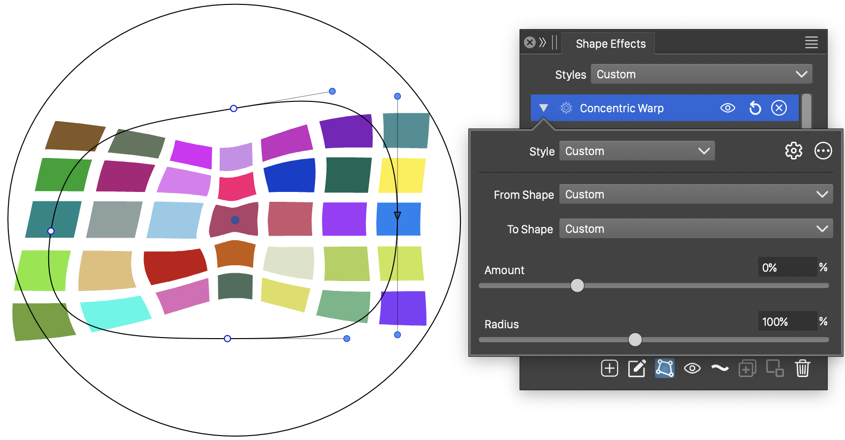
The Concentric Warp distortion, with basic options.
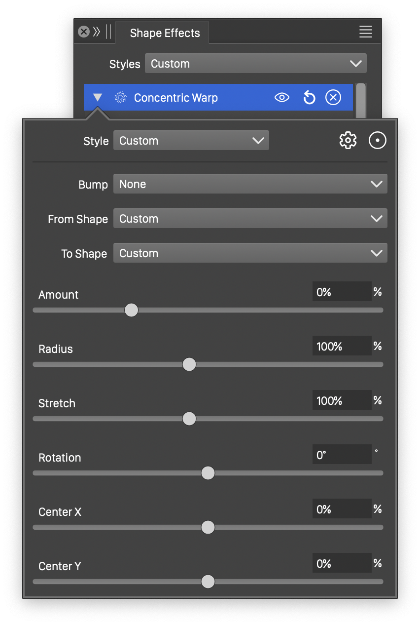
Detailed options of the Concentric Warp distortion.
The Concentric Warp distortion effect uses the following basic options:
- From Shape - Select the origin shape, from the list of shape presets, styles and object references with the Shape role. The origin shape can be edited using the path editor, by clicking on the button in the icon section of the panel.
- To Shape - Select the target shape, from the list of shape presets, styles and object references with the Shape role. The target shape can be edited using the path editor, by clicking on the button in the icon section of the panel.
- Amount - Set the amount of bump distortion from the center. The default distortion is set to 0%, resulting in no bump stretching. For values larger than 0%, the distortion stretches the shapes outwards from the center. For values smaller than 0%, the distortion stretches the shapes inwards to the center.
- Radius - Set the radius of the distorted area. The distortion affects shapes inside this radius around the center.
More detailed options of the Concentric Warp distortion are available, by clicking on the button.
- Bump - Select a function for the bump stretching transition. The Cubic and Monotone Cubic functions are edited by selecting the Edit Curve command.
- Stretch - Stretch the distortion region vertically, creating an elliptical distortion region.
- Rotation - Set the rotation of the distortion region shape.
- Center X and Center Y - Set the center of the distortion shape, relative to the object frame. The center can also be adjusted visually using the primary shape effect editor tool.
The button from the Shape Effects panel, activates the shape effect tool used to interactively edit the concentric warp distortion attributes.
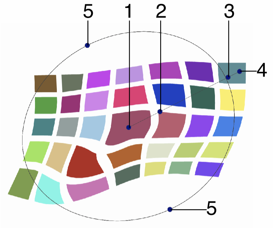
Interactive editing of the Concentric Warp distortion.
Interactive editing of the concentric warp distortion is done by dragging the handles to change an attribute value:
- (1) - Set the center of the distortion region.
- (2) - Set the amount of distortion, by dragging this handle along the axis of the distortion.
- (3) - Set the radius of the distortion, by dragging this handle towards or away from the center.
- (4) - Set the rotation of the distortion, by dragging this handle around the center.
- (5) - Set the vertical stretching of the distortion region, by dragging this handle towards or away from the center.
The concentric warp origin and target shapes can be edited as regular paths using the secondary shape effect tool from the icon section of the panel. When the secondary shape effect tool is active, the origin and target shape nodes are shown and can be adjusted using regular path editing commands.
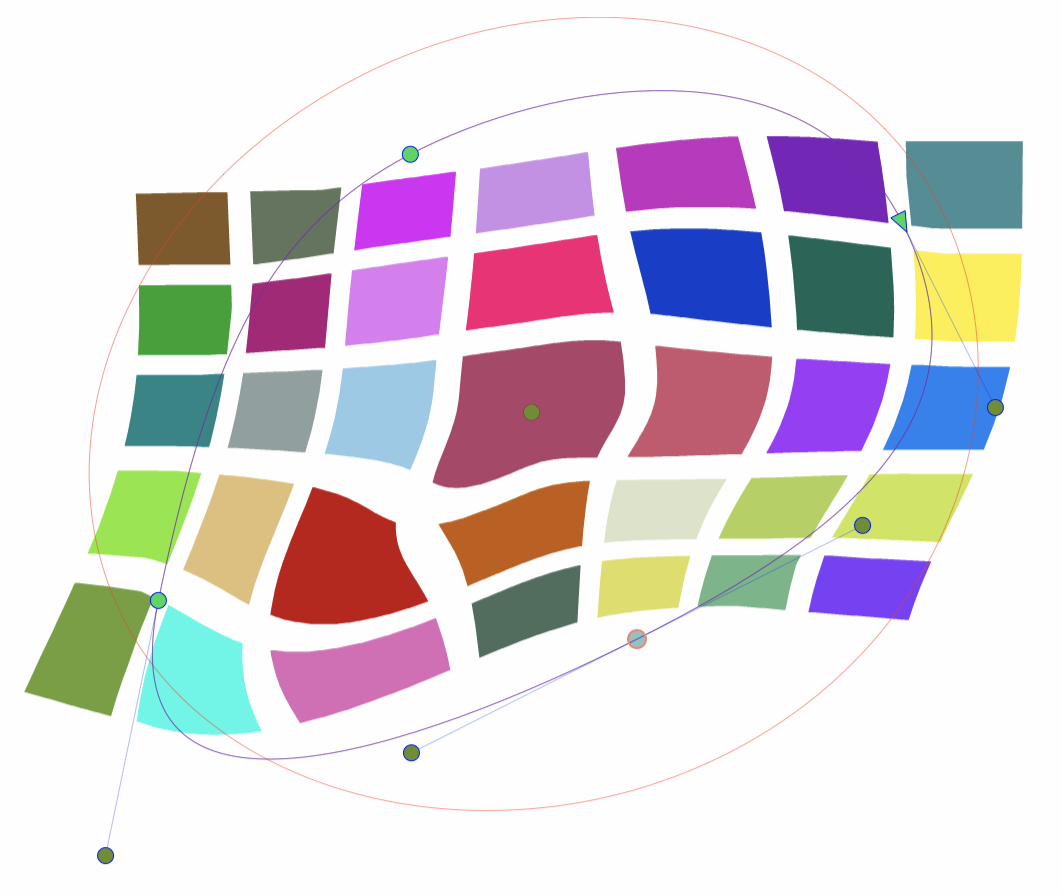
Editing the origin and target shapes of the Concentric Warp distortion.
Hole
The Hole distortion effect expands a hole around the center of the distortion, stretching the shape out from an inner radius. The size of the hole is the inner radius of the distortion. The shape of the hole can be set to any user defined shape.
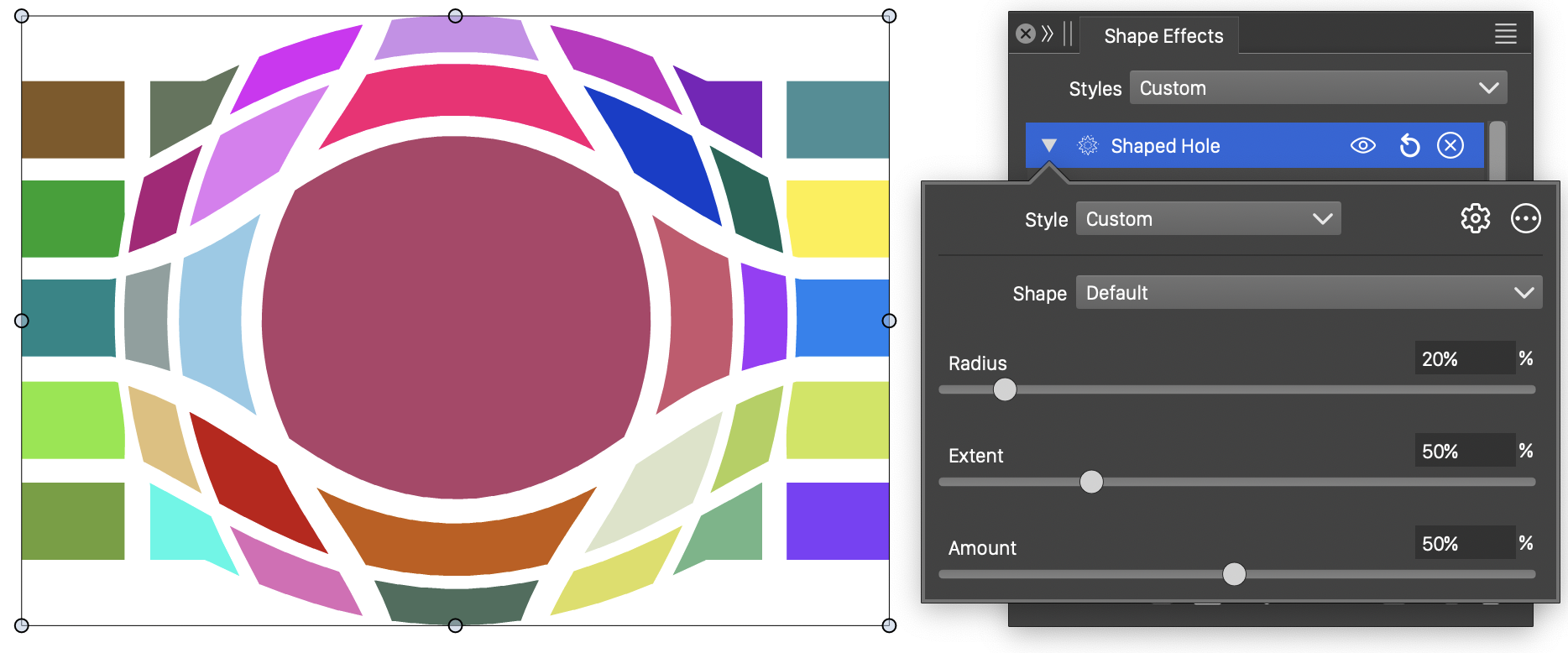
The Hole distortion, with basic options.
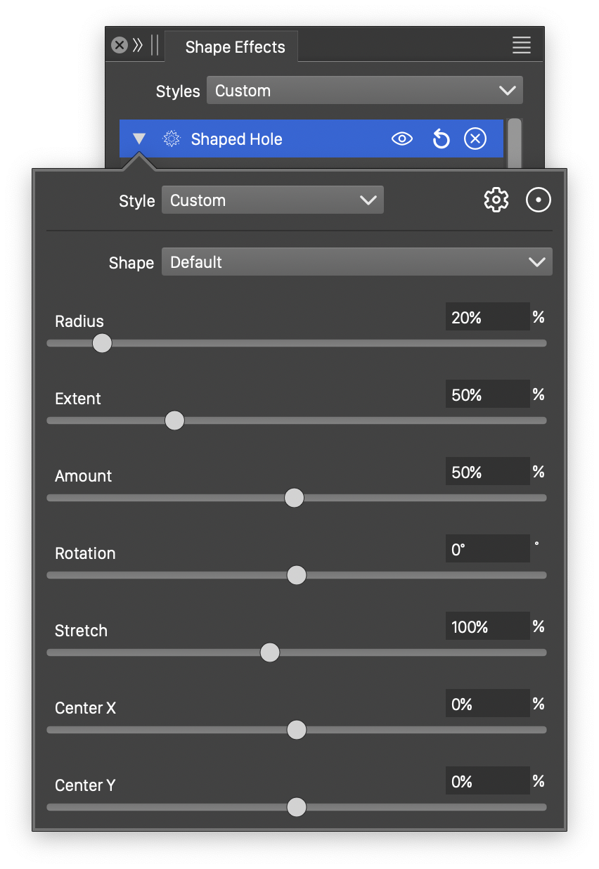
Detailed options of the Hole distortion.
The Hole distortion effect uses the following basic options:
- Shape - Select the shape of the hole, from the list of shape presets, styles and object references with the Shape role. The shape can be edited using the path editor, by clicking on the button in the icon section of the panel.
- Radius - Set the inner radius of the hole distortion.
- Extent - Set the extent of the hole distortion. The extent determines the region of the objects adjusted by the hole distortion.
- Amount - Set the hole distortion amount. Smaller values result in larger distortion and more stretching of the shape outward from the hole.
More detailed options of the Hole distortion are available, by clicking on the button.
- Rotation - Set the rotation of the hole distortion.
- Stretch - Stretch the hole distortion vertically, creating an elliptical distortion region.
- Center X and Center Y - Set the center of the hole distortion, relative to the object frame. The center can also be adjusted visually using the primary shape effect editor tool.
The button from the Shape Effects panel, activates the shape effect tool used to interactively edit the hole distortion attributes.
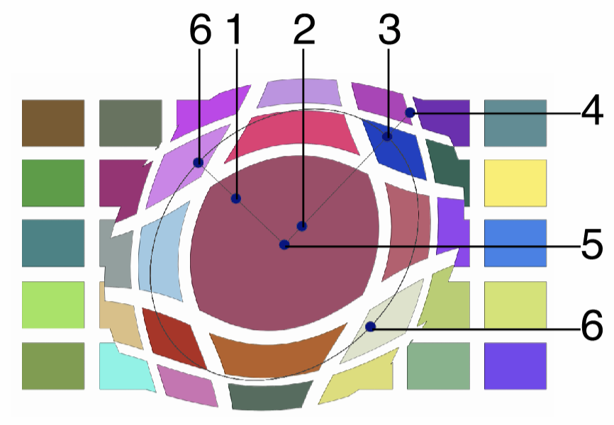
Interactive editing of the Hole distortion.
Interactive editing of the hole distortion is done by dragging the handles to change an attribute value:
- (1) - Adjust the amount of the hole distortion, by dragging this towards or away from the center.
- (2) - Adjust the inner radius of the hole distortion, by dragging this towards or away from the center.
- (3) - Adjust the extent of the hole distortion, by dragging this towards or away from the center.
- (4) - Set the rotation of the hole distortion, by dragging this handle around the center.
- (5) - Set the center of the hole distortion.
- (6) - Set the vertical stretching of the distortion region, by dragging this handle towards or away from the center.
The hole distortion shape can be edited as a regular path using the secondary shape effect tool from the icon section of the panel. When the secondary shape effect tool is active, the hole shape nodes are shown and can be adjusted using regular path editing commands.
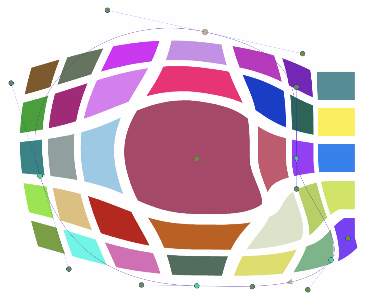
Editing the shape of the Hole distortion.
Noise Wave
The Noise Wave distortion effect adds random waving to the object shapes using a synthetic noise to locally vary the strength of the waving. The Noise Wave distortion is similar to the Wave distortion, with the difference, that the waving strength is augmented by a noise style. Using fixed noise positioning, will make the waving style to change based on the object location.
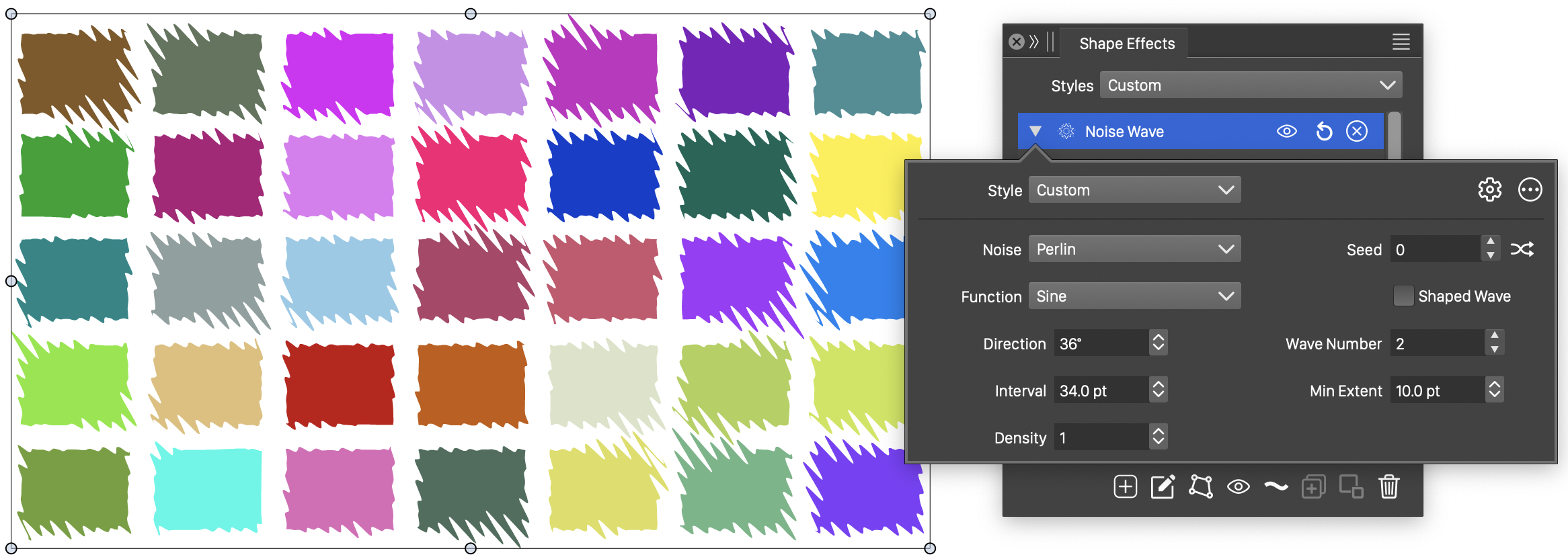
The Noise Wave distortion, with basic options.
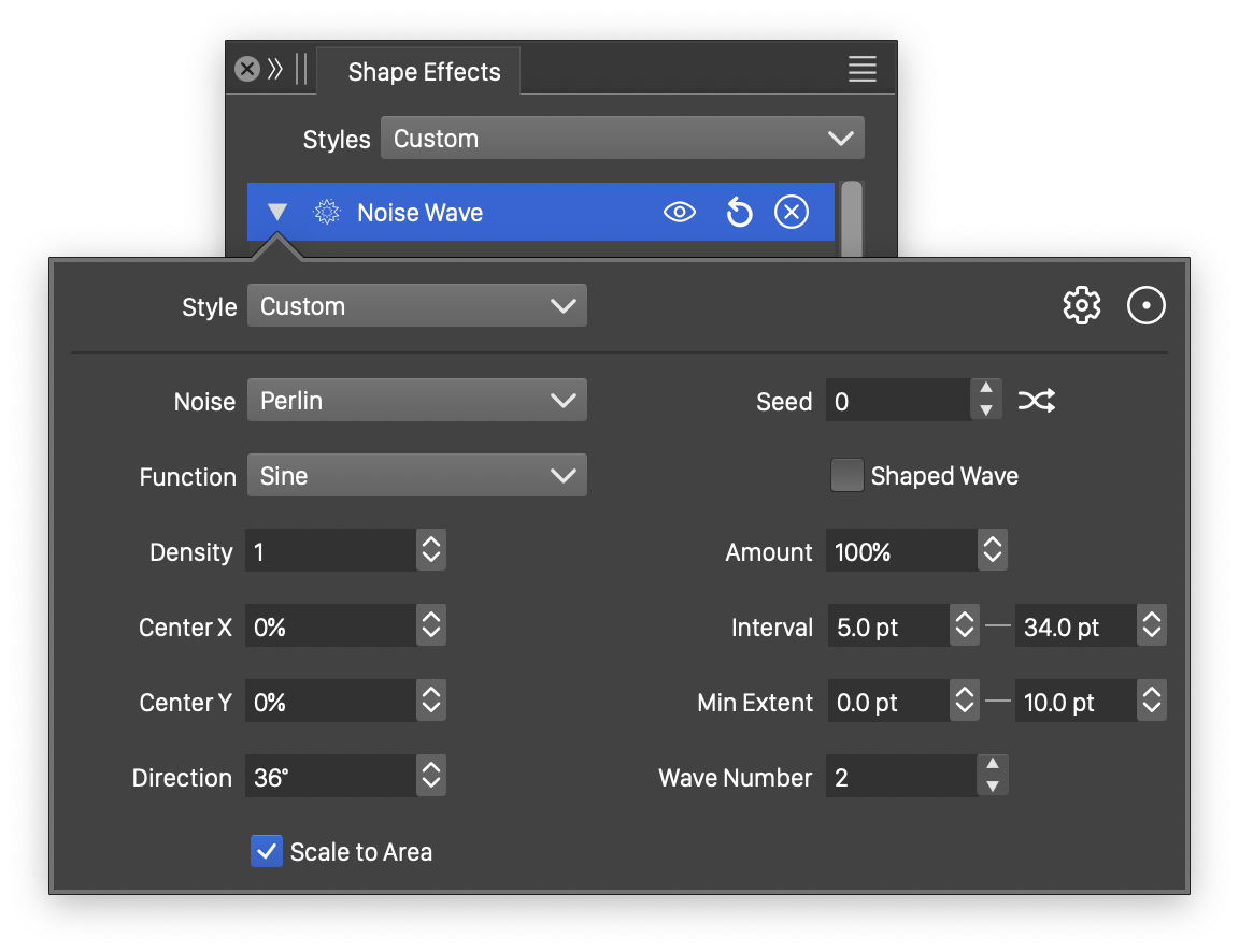
Detailed options of the Noise Wave distortion.
The Noise Wave distortion effect uses the following basic options:
- Noise - Select the noise style from the list of predefined noise types, or user defined noise presets and styles. To browse randomly generated synthetic noise styles, select the Browse Styles command. To edit the noise attributes, select the Edit Noise command. Selecting noise is described with more detail in the Noise chapter.
- Function - Edit the wave variation function. This option is visible if the Shaped Wave is not checked. The Edit Curve command opens the function editor view to edit cubic or monotone functions, defining the waving in the distortion.
- Shape - Select a shape preset or style, used for the wave variation. This option is visible if the Shaped Wave is checked. The shape can be edited using the path editor, by clicking on the button in the icon section of the panel.
- Density - Edit the noise density. Higher values result in lower frequency noise.
- Direction - Set the noise waving direction. The direction can also be adjusted interactively, using the primary shape effect editor tool.
- Max Interval - Set the maximum interval of the waving. Larger values result in longer waves.
- Max Extent - Set the maximum extent of the noise waving. The amplitude controls the height of a wave.
- Wave Number - Set the number of waves used to create the waving effect.
- Seed - Set the randomization seed used to generate waves. The
 button can be used to pick random seed values.
 - Shaped Wave - Enable or disable the use of a shape (instead of a function) to control the waving distortion. When enabled, the Shape field is used to select a shape preset or style. When disabled, the Function field is used to control the waving.
More detailed options of the Noise Wave distortion are available, by clicking on the button.
- Amount - Set the amount of noise used to adjust the waving strength.
- Center X and Center Y - Set the center of the noise wave distortion, relative to the object frame. The center can also be adjusted visually using the primary shape effect editor tool.
- Min Interval - Set the shortest wave length of the distortion.
- Min Extent - Set the shortest wave extent of the distortion.
- Scale to Area - Enable or disable the scaling of the selected wave shape to the filtered area.
The button from the Shape Effects panel, activates the shape effect tool used to interactively edit the noise wave distortion attributes.
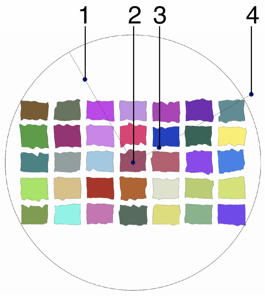
Interactive editing of the Noise Wave distortion.
Interactive editing of the noise wave distortion is done by dragging the handles to change an attribute value:
- (1) - Adjust the maximum amplitude of the waving.
- (2) - Set the center of the noise wave distortion.
- (3) - Adjust the maximum interval of the waving.
- (4) - Set the rotation of the noise wave distortion, by dragging this handle around the center.
The shape used in the noise wave distortion, can be edited as a regular path using the secondary shape effect tool from the icon section of the panel. When the secondary shape effect tool is active, the wave shape nodes are shown and can be adjusted using regular path editing commands.
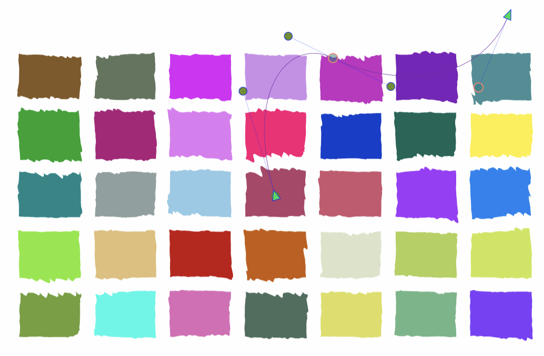
Editing the shape of the Noise Wave distortion.
Noise Zigzag
The Noise Zigzag effect adds a random jagged distortion to the object shapes using a synthetic noise to locally vary the extend of the jagged stretching. The Noise Zigzag distortion is similar to the Zigzag distortion, with the difference, that the jaggedness strength is augmented by a noise style, and the wave interval and extent is random. Using fixed noise positioning, will make the waving style to change based on the object location.
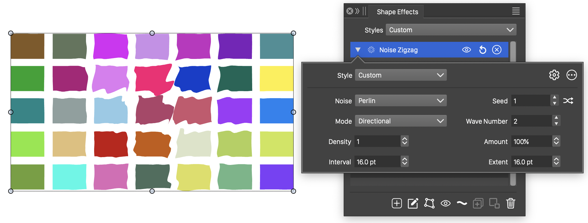
The Noise Zigzag distortion, with basic options.
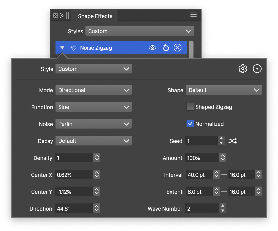
Detailed options of the Noise Zigzag distortion.
The Noise Zigzag distortion effect uses the following basic options:
- Noise - Select the noise style from the list of predefined noise types, or user defined noise presets and styles. To browse randomly generated synthetic noise styles, select the Browse Styles command. To edit the noise attributes, select the Edit Noise command. Selecting noise is described with more detail in the Noise chapter.
- Mode - Select the jaggedness mode, controlling the direction of the jagged waves. This can be:
- Angular - The jagged waves are stretching around the center, adjusting the angle, but not the distance, of a shape location relative to the center.
- Concentric - The jagged waves are stretching to or from the center, adjusting the distance, but not the angle, of a shape location relative to the center.
- Directional - The jagged waves are adjusting the shape at a specific direction, set in the Direction field.
- Amount - Set the amount of noise used to adjust the jaggedness strength.
- Density - Edit the noise density. Higher values result in lower frequency noise.
- Interval - Set the interval of the jaggedness. Larger values result in longer period of the waves.
- Extent - Set the extent of the noise jaggedness. The amplitude controls the height of a wave.
More detailed options of the Noise Zigzag distortion are available, by clicking on the button.
- Decay - Edit the wave decay function. The Edit Curve command opens the function editor view to edit cubic or monotone functions, defining the amount of decay of the wave extent towards the edge of the region.
- Function - Edit the zigzag variation function. This option is visible if the Shaped Zigzag is not checked. The Edit Curve command opens the function editor view to edit cubic or monotone functions, defining the strength of the jaggedness in the distortion.
- Wave - Select a shape preset or style, used for the zigzag variation. This option is visible if the Shaped Zigzag is checked.
- Shape - Select a shape preset or style, used as the zigzag direction shape. The zigzag shape controls the direction of the jagged waves. The shape can be edited interactively using the path editor, by clicking on the button in the icon section of the panel.
- Center X and Center Y - Set the center of the noise zigzag distortion, relative to the object frame. The center can also be adjusted visually using the primary shape effect editor tool.
- Direction - Set the noise zigzag direction. The direction angle is used when the jaggedness mode is set to Directional. The direction can also be adjusted interactively, using the primary shape effect editor tool.
- Min Interval - Set the shortest wave length of the distortion.
- Max Interval - Set the maximum interval of the jaggedness. Larger values result in longer period of the waves.
- Min Extent - Set the shortest wave extent of the distortion.
- Max Extent - Set the maximum extent of the noise jaggedness. The amplitude controls the height of a wave.
- Wave Number - Set the number of waves used to create the jaggedness effect.
- Seed - Set the randomization seed used to generate jaggedness. The button can be used to pick random seed values.
- Shaped Zigzag - Enable or disable the use of a shape (instead of a function) to control the zigzag distortion. When enabled, the Shape field is used to select a shape preset or style. When disabled, the Function field is used to control the jaggedness.
- Normalized - Enable or disable the use of normalized noise amounts.
The button from the Shape Effects panel, activates the shape effect tool used to interactively edit the noise zigzag distortion attributes.
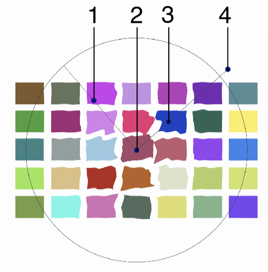
Interactive editing of the Noise Zigzag distortion.
Interactive editing of the noise zigzag distortion is done by dragging the handles to change an attribute value:
- (1) - Adjust the maximum amplitude of the jaggedness.
- (2) - Set the center of the noise zigzag distortion.
- (3) - Adjust the maximum interval of the jaggedness.
- (4) - Set the rotation of the noise zigzag distortion, by dragging this handle around the center.
The shape used in the noise zigzag distortion, can be edited as a regular path using the secondary shape effect tool from the icon section of the panel. When the secondary shape effect tool is active, the shape nodes are shown and can be adjusted using regular path editing commands.
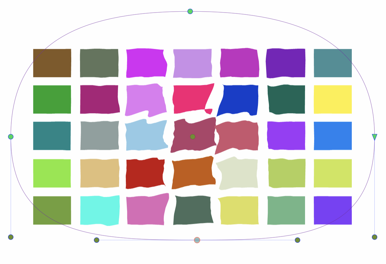
Editing the shape of the Noise Zigzag distortion.
Perturbation
The Perturbation effect adds a synthetic noise based random perturbation to the object shapes. The perturbation is added to the shapes, by shifting points on the shape horizontally or vertically, using amounts generated by the noise. The horizontal and vertical shifting is adjusted by the direction of the perturbation.
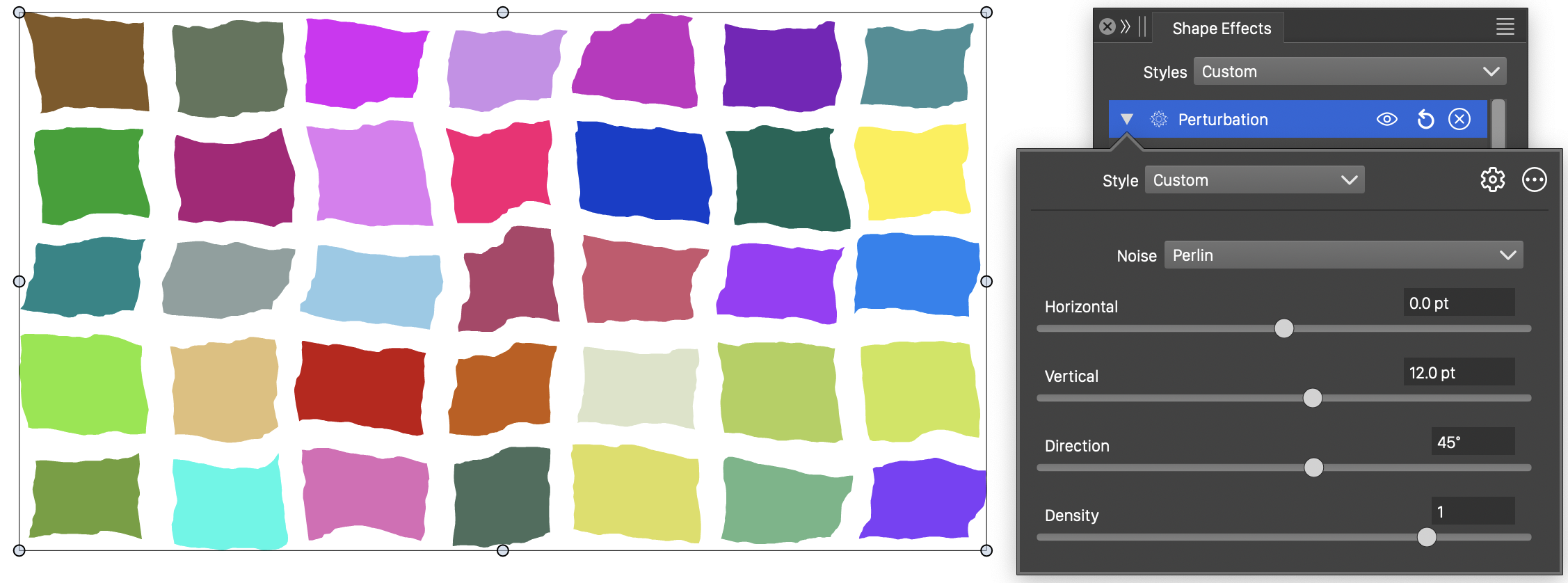
The Perturbation distortion, with basic options.
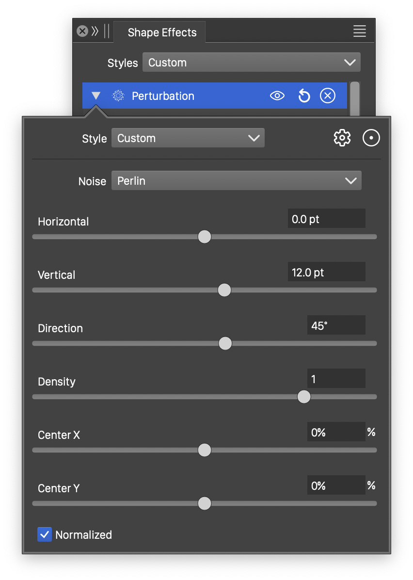
Detailed options of the Perturbation distortion.
The Perturbation distortion effect uses the following basic options:
- Noise - Select the noise style from the list of predefined noise types, or user defined noise presets and styles. To browse randomly generated synthetic noise styles, select the Browse Styles command. To edit the noise attributes, select the Edit Noise command. Selecting noise is described with more detail in the Noise chapter.
- Horizontal - Set the amount of horizontal perturbation. The direction of the horizontal perturbation is determined by the angle set in the Direction field.
- Vertical - Set the amount of vertical perturbation. The direction of the vertical perturbation is determined by the angle set in the Direction field.
- Density - Edit the noise density. Higher values result in lower frequency noise.
More detailed options of the Perturbation distortion are available, by clicking on the button.
- Center X and Center Y - Set the center of the distortion, relative to the object frame. The center can also be adjusted visually using the primary shape effect editor tool.
- Normalized - Enable or disable the use of normalized noise amounts.
The button from the Shape Effects panel, activates the shape effect tool used to interactively edit the Perturbation distortion attributes.
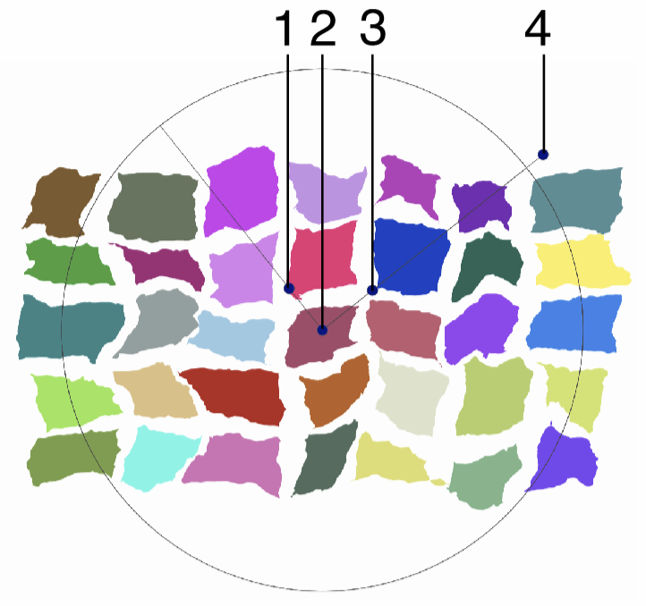
Interactive editing of the Perturbation distortion.
Interactive editing of the Perturbation distortion is done by dragging the handles to change an attribute value:
- (1) - Adjust the extent of the vertical perturbation.
- (2) - Set the center of the distortion region.
- (3) - Adjust the extent of the horizontal perturbation.
- (4) - Set the direction of the distortion, by dragging this handle around the center.
Polar Map
The Polar Map distortion effect converts the shape coordinates from rectangular to polar, or from polar to rectangular.
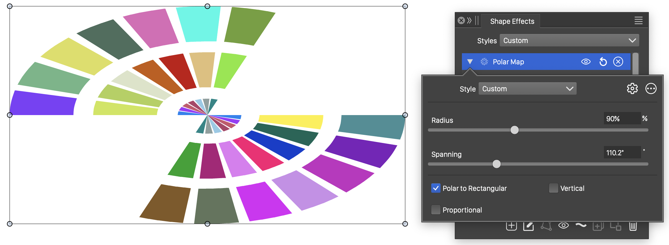
The Polar Map distortion, with basic options.
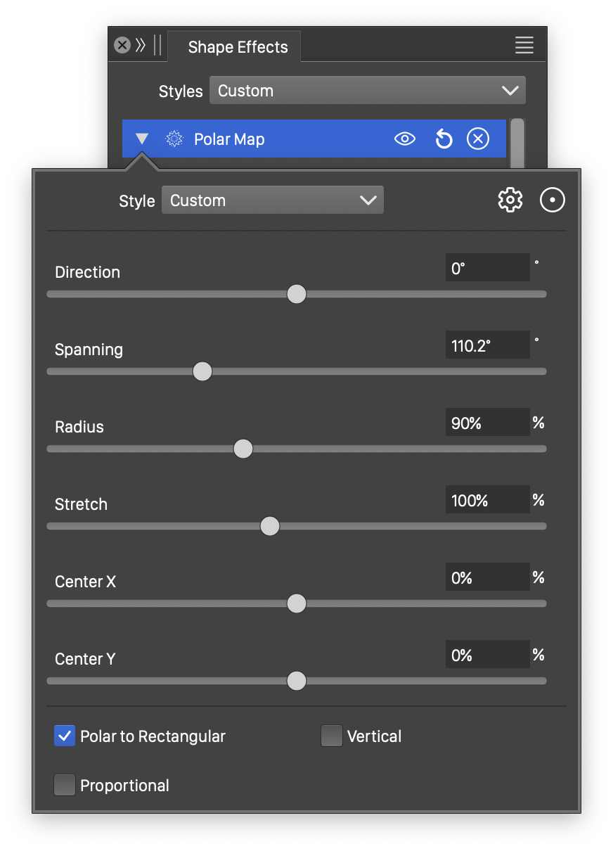
Detailed options of the Polar Map distortion.
The Polar Map distortion effect uses the following basic options:
- Radius - Set the radius of the polar coordinate space. The radius is used to map the height of the object in the rectangular coordinate space to a radius.
- Spanning - Edit the angular spanning of the polar coordinate space.
- Proportional - Enables or disables the proportional mapping between rectangular and polar coordinate spaces.
- Vertical - Enables or disables the mapping of the vertical axis to the angular axis of the polar coordinate space.
- Polar to Rectangular - Enables or disables polar to rectangular mapping. When enabled, polar coordinates are mapped to rectangular coordinates.
More detailed options of the Polar Map distortion are available, by clicking on the button.
- Direction - Set the direction of the polar to rectangular mapping.
- Stretch - Set vertical stretching of the polar coordinate space into an ellipse.
- Center X and Center Y - Set the center of the distortion, relative to the object frame. The center can also be adjusted visually using the primary shape effect editor tool.
The button from the Shape Effects panel, activates the shape effect tool used to interactively edit the Polar Map distortion attributes.
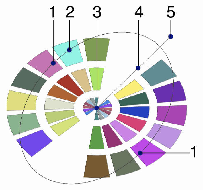
Interactive editing of the Polar Map distortion.
Interactive editing of the Polar Map distortion is done by dragging the handles to change an attribute value:
- (1) - Adjust the vertical stretching of the polar coordinate space.
- (2) - Adjust the spanning angle of the polar coordinate space.
- (3) - Set the center of the polar and rectangular coordinate spaces.
- (4) - Adjust the radius of the polar coordinate space.
- (5) - Set the direction of the distortion, by dragging this handle around the center.
Random Zigzag
The Random Zigzag effect adds a random jagged distortion to the object shapes, at a user selected direction. The Random Zigzag distortion is similar to the Noise Zigzag distortion, except here, there is no noise adjusting the distortion strength locally.
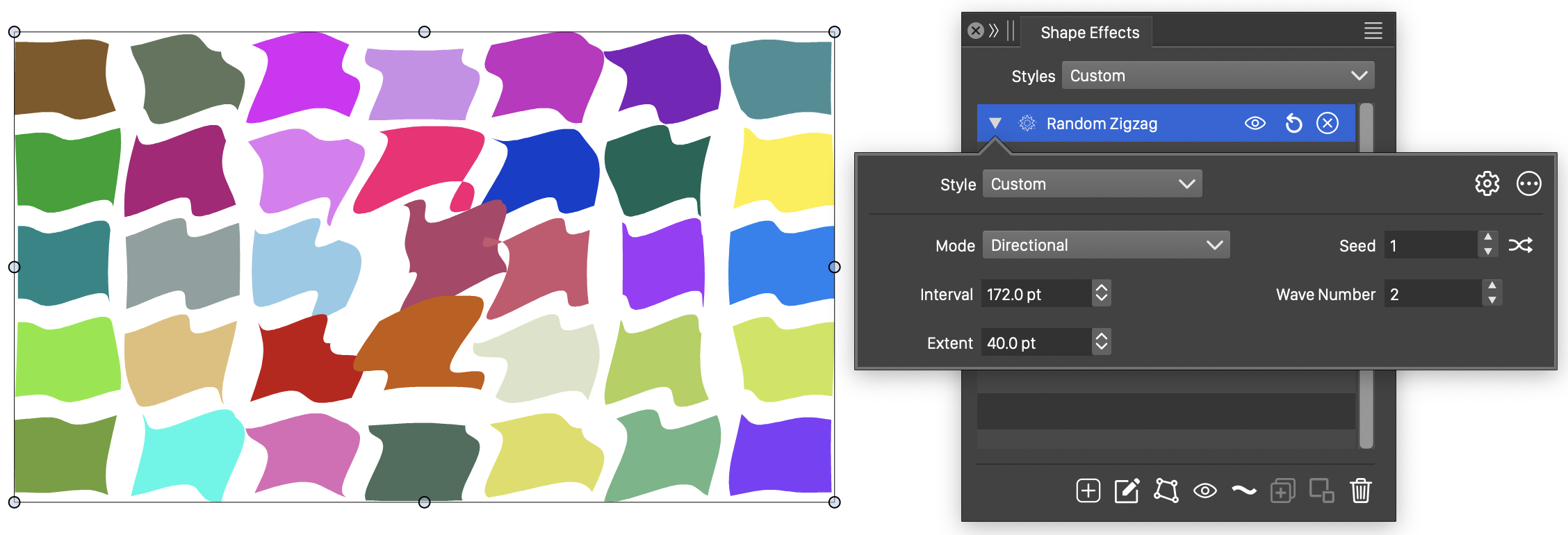
The Random Zigzag distortion, with basic options.
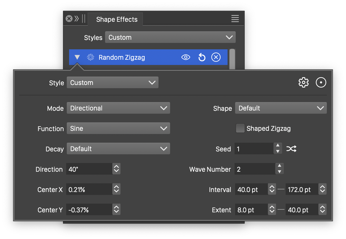
Detailed options of the Random Zigzag distortion.
The Random Zigzag distortion effect uses the following basic options:
- Mode - Select the jaggedness mode, controlling the direction of the jagged waves. This can be:
- Angular - The jagged waves are stretching around the center, adjusting the angle, but not the distance, of a shape location relative to the center.
- Concentric - The jagged waves are stretching to or from the center, adjusting the distance, but not the angle, of a shape location relative to the center.
- Directional - The jagged waves are adjusting the shape at a specific direction, set in the Direction field.
- Max Interval - Set the maximum interval of the jaggedness. Larger values result in longer period of the waves.
- Max Extent - Set the maximum extent of the noise jaggedness. The amplitude controls the height of a wave.
- Wave Number - Set the number of waves used to create the jaggedness effect.
- Seed - Set the randomization seed used to generate jaggedness. The button can be used to pick random seed values.
More detailed options of the Random Zigzag distortion are available, by clicking on the button.
- Decay - Edit the wave decay function. The Edit Curve command opens the function editor view to edit cubic or monotone functions, defining the amount of decay of the wave extent towards the edge of the region.
- Function - Edit the zigzag variation function. This option is visible if the Shaped Zigzag is not checked. The Edit Curve command opens the function editor view to edit cubic or monotone functions, defining the strength of the jaggedness in the distortion.
- Wave - Select a shape preset or style, used for the zigzag variation. This option is visible if the Shaped Zigzag is checked.
- Shape - Select a shape preset or style, used as the zigzag direction shape. The zigzag shape controls the direction of the jagged waves. The shape can be edited interactively using the path editor, by clicking on the button in the icon section of the panel.
- Center X and Center Y - Set the center of the zigzag distortion, relative to the object frame. The center can also be adjusted visually using the primary shape effect editor tool.
- Direction - Set the zigzag direction. The direction angle is used when the jaggedness mode is set to Directional. The direction can also be adjusted interactively, using the primary shape effect editor tool.
- Min Interval - Set the shortest wave length of the distortion.
- Min Extent - Set the shortest wave extent of the distortion.
- Shaped Zigzag - Enable or disable the use of a shape (instead of a function) to control the zigzag distortion. When enabled, the Shape field is used to select a shape preset or style. When disabled, the Function field is used to control the jaggedness.
The button from the Shape Effects panel, activates the shape effect tool used to interactively edit the random zigzag distortion attributes.
Interactive editing of the Random Zigzag distortion.
Interactive editing of the random zigzag distortion is done by dragging the handles to change an attribute value:
- (1) - Adjust the maximum amplitude of the jaggedness.
- (2) - Set the center of the zigzag distortion.
- (3) - Adjust the maximum interval of the jaggedness.
- (4) - Set the rotation of the zigzag distortion, by dragging this handle around the center.
The shape used in the random zigzag distortion, can be edited as a regular path using the secondary shape effect tool from the icon section of the panel. When the secondary shape effect tool is active, the shape nodes are shown and can be adjusted using regular path editing commands.
Editing the shape of the Random Zigzag distortion.
Ripple
The Ripple effect adds a synthetic noise based ripple distortion to the object shapes. The ripple distortion is added to the shapes, by adjusting the radial and angular positions of the points on a shape, using amounts generated by the noise.
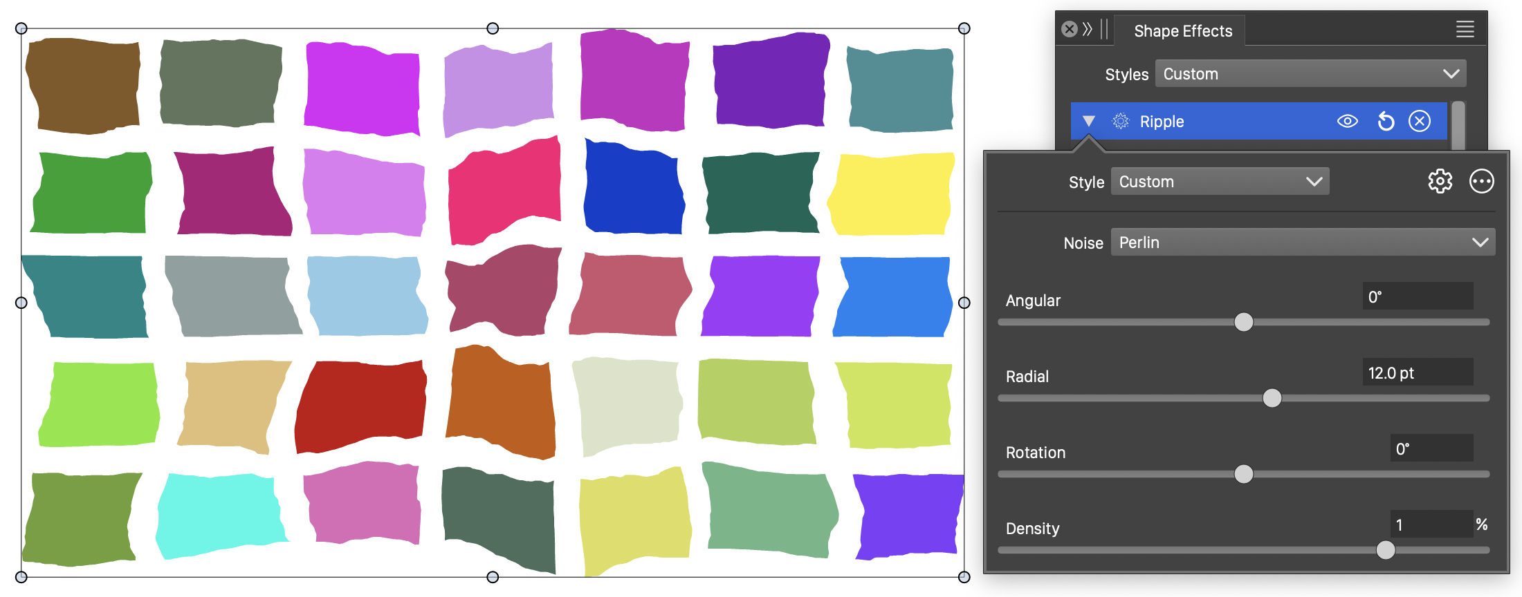
The Ripple distortion, with basic options.
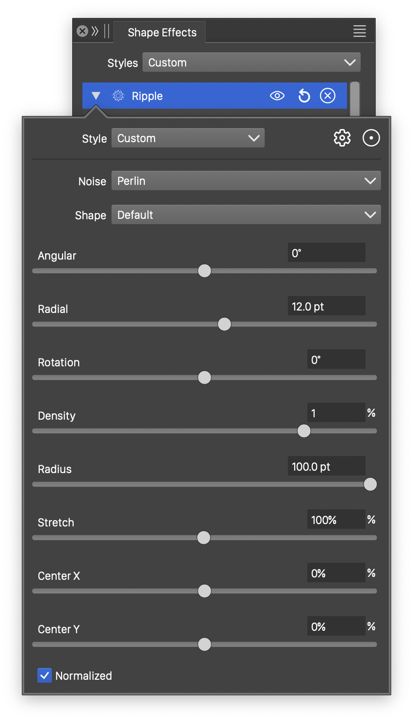
Detailed options of the Ripple distortion.
The Ripple distortion effect uses the following basic options:
- Noise - Select the noise style from the list of predefined noise types, or user defined noise presets and styles. To browse randomly generated synthetic noise styles, select the Browse Styles command. To edit the noise attributes, select the Edit Noise command. Selecting noise is described with more detail in the Noise chapter.
- Shape - Select a shape preset or style, used as the ripple shape. The shape can be edited interactively using the path editor, by clicking on the button in the icon section of the panel.
- Angular - Set the amount of angular ripple distortion.
- Radial - Set the amount of radial ripple distortion.
- Direction - Set the angle of the ripple distortion.
- Density - Edit the noise density. Higher values result in lower frequency noise.
More detailed options of the Ripple distortion are available, by clicking on the button.
- Radius - Set the radius of the ripple distortion region.
- Stretch - Edit the vertical stretching of the ripple region, resulting in an elliptic ripple distortion.
- Center X and Center Y - Set the center of the distortion, relative to the object frame. The center can also be adjusted visually using the primary shape effect editor tool.
- Normalized - Enable or disable the use of normalized noise amounts.
The button from the Shape Effects panel, activates the shape effect tool used to interactively edit the Ripple distortion attributes.
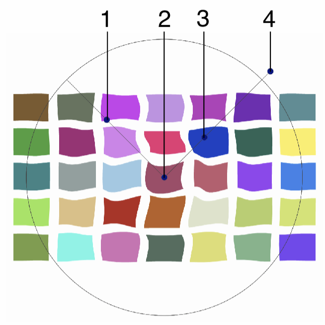
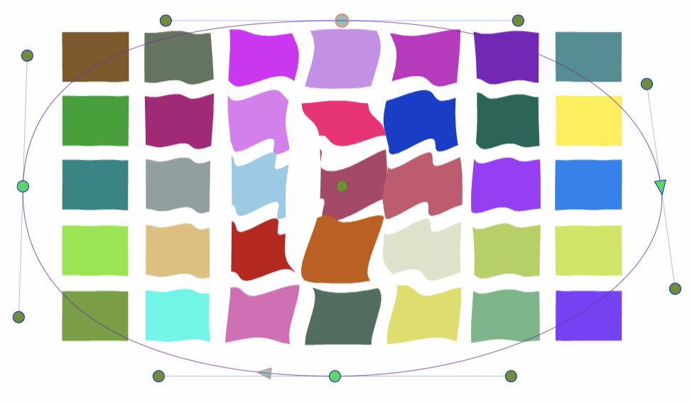
Interactive editing of the Ripple distortion.
Interactive editing of the Ripple distortion is done by dragging the handles to change an attribute value:
- (1) - Adjust the extent of the angular ripple distortion.
- (2) - Adjust the vertical stretching of the ripple region.
- (3) - Adjust the extent of the radial ripple distortion.
- (4) - Adjust the radius of the ripple distortion.
- (5) - Set the rotation of the ripple distortion, by dragging this handle around the center.
- (6) - Set the center of the ripple distortion.
The shape used in the ripple distortion, can be edited as a regular path using the secondary shape effect tool from the icon section of the panel. When the secondary shape effect tool is active, the shape nodes are shown and can be adjusted using regular path editing commands.
Editing the shape of the Ripple distortion.
Shape Bump
The Shape Bump distortion effect stretches the shapes of objects in a concentric direction around a distortion center, inwards or outwards, using a shape to control the local amount of stretching.
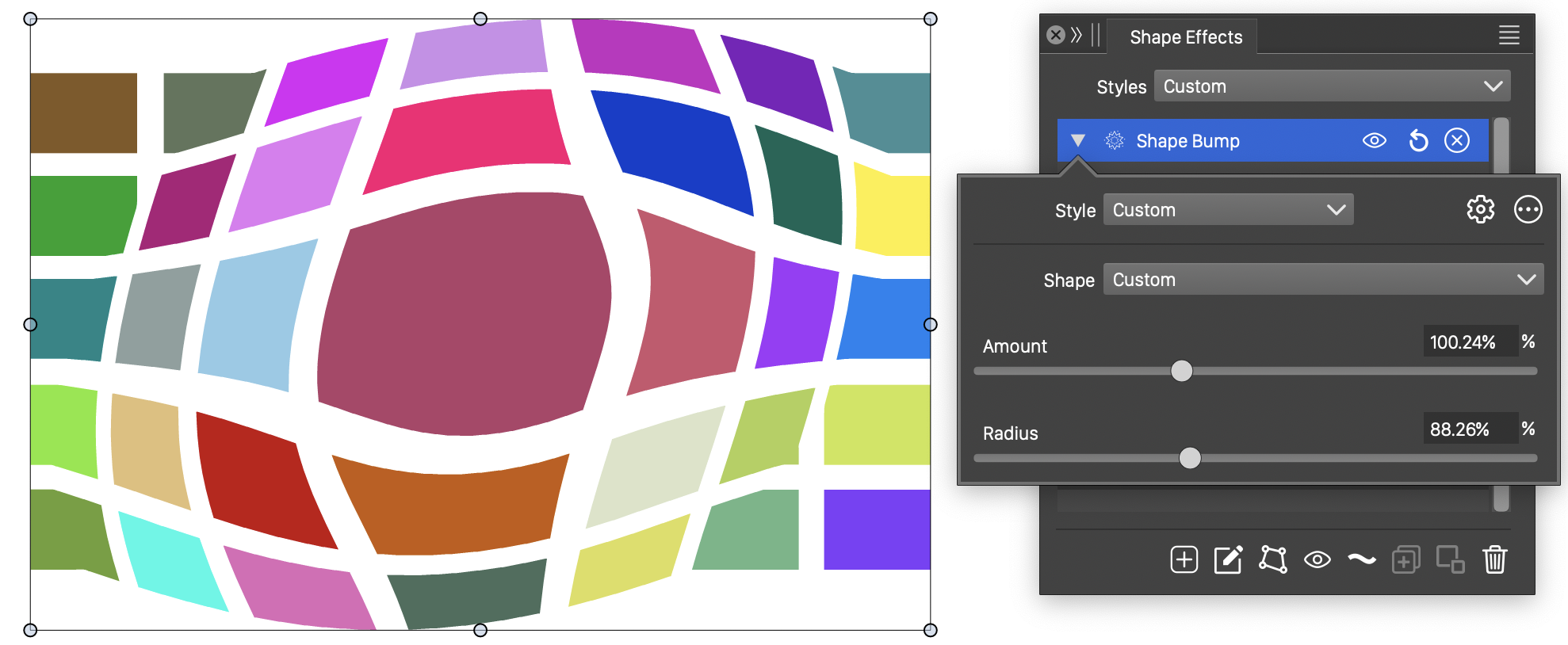
The Shape Bump distortion, with basic options.
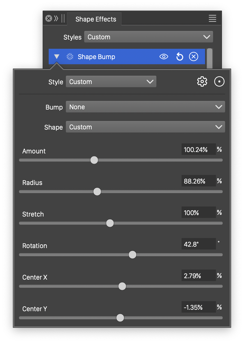
Detailed options of the Shape Bump distortion.
The Shape Bump distortion effect uses the following basic options:
- Shape - Select a shape preset or style, used in the bump distortion. The shape can be edited using the path editor, by clicking on the button in the icon section of the panel.
- Amount - Set the amount of bump distortion. For values larger than 0%, the distortion stretches the shapes outwards from the center. For values smaller than 0%, the distortion stretches the shapes inwards to the center.
- Radius - Set the radius of the distorted area. The distortion affects shapes inside this radius around the center.
More detailed options of the Shape Bump distortion are available, by clicking on the button.
- Bump - Select a function for the bump stretching transition. The Cubic and Monotone Cubic functions are edited by selecting the Edit Curve command.
- Stretch - Stretch the distortion shape vertically, creating a stretched distortion region.
- Rotation - Set the rotation of the distortion shape.
- Center X and Center Y - Set the center of the distortion shape, relative to the object frame. The center can also be adjusted visually using the primary shape effect editor tool.
The button from the Shape Effects panel, activates the shape effect tool used to interactively edit the shape bump distortion attributes.

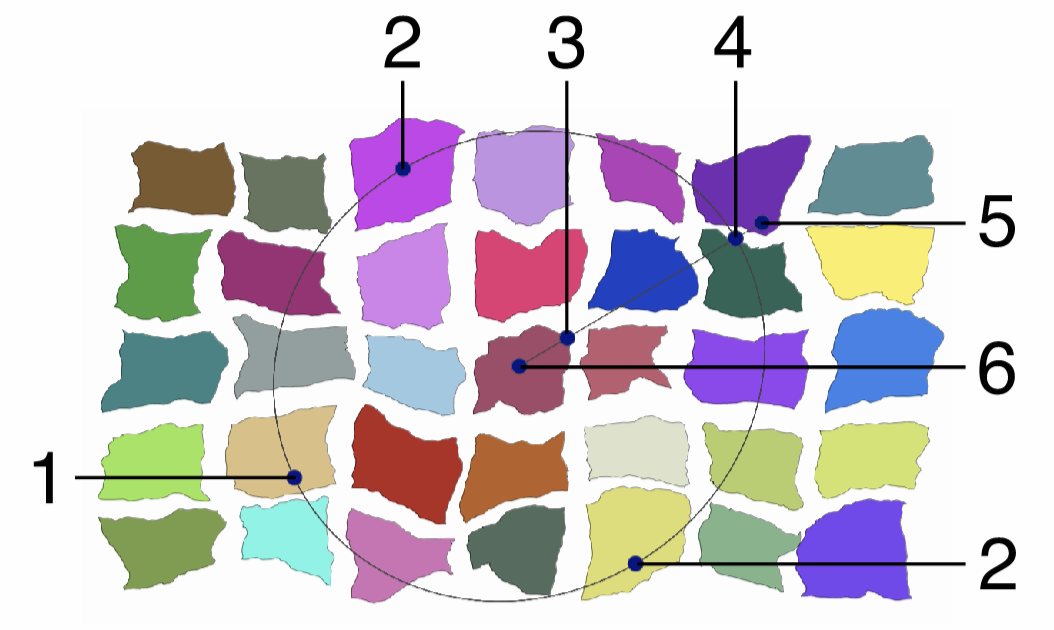
Interactive editing of the Shape Bump distortion.
Interactive editing of the shape bump distortion is done by dragging the handles to change an attribute value:
- (1) - Set the center of the distortion region.
- (2) - Set the amount of distortion, by dragging this handle along the axis of the distortion.
- (3) - Set the radius of the distortion, by dragging this handle towards or away from the center.
- (4) - Set the rotation of the distortion, by dragging this handle around the center.
- (5) - Set the vertical stretching of the distortion region, by dragging this handle towards or away from the center.
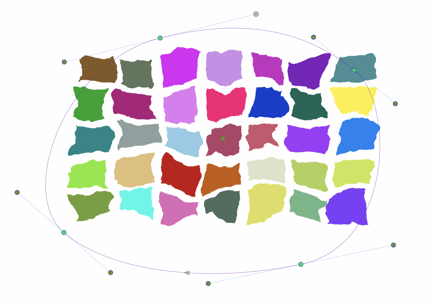
The shape used in the shape bump distortion, can be edited as a regular path using the secondary shape effect tool from the icon section of the panel. When the secondary shape effect tool is active, the shape nodes are shown and can be adjusted using regular path editing commands.
Editing the shape of the Shape Bump distortion.
Shear
The Shear distortion effect shifts the object shapes along a user defined curve or shape. The shear distortion can be along a user defined function to define the shifting of the points, or along a user defined shape.
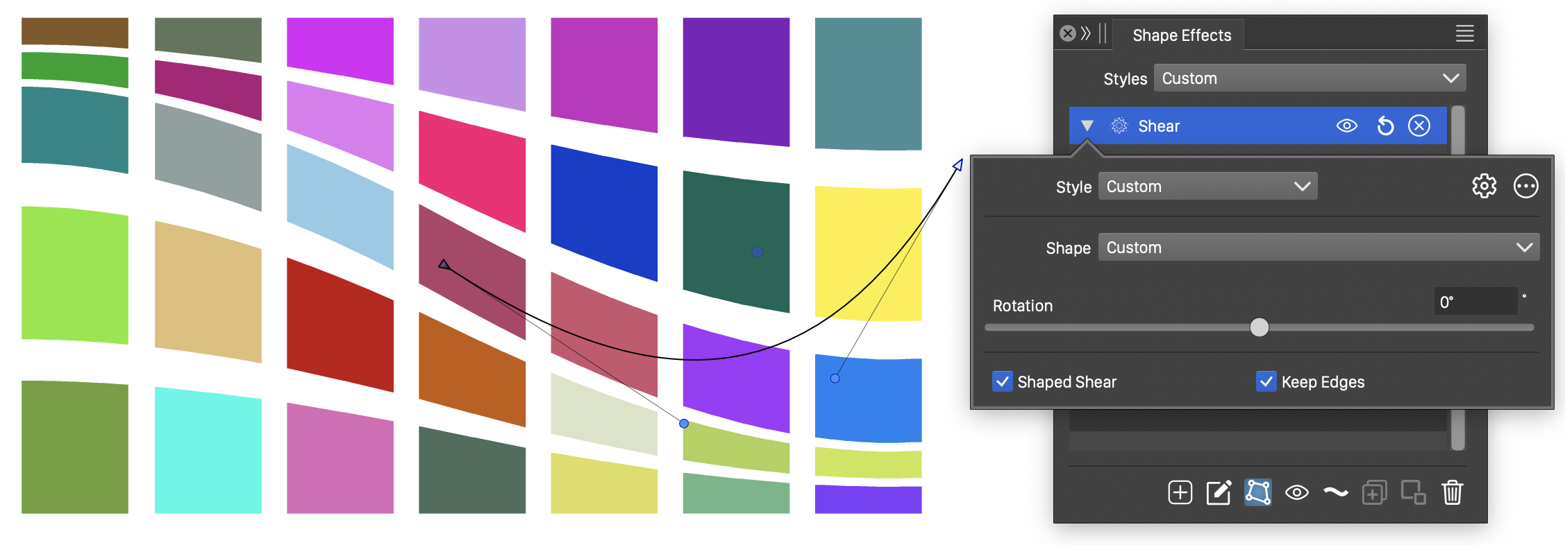
The Shear distortion, with basic options.
Detailed options of the Shear distortion.
The Shear distortion effect uses the following basic options:
- Function - Edit the shear distortion function. This option is visible if the Shaped Shear is not checked. The Edit Curve command opens the function editor view to edit cubic or monotone functions, defining the waving in the distortion.
- Shape - Select a shape preset or style, used in the shear distortion. The shape can be edited using the path editor, by clicking on the button in the icon section of the panel.
- Rotation - Sets the direction of the shear distortion. By default, the shifting of points is along the vertical axis. Rotating the shear distortion will rotate the shifting direction.
- Shaped Shear - Enable or disable the use of shape in the shear distortion.
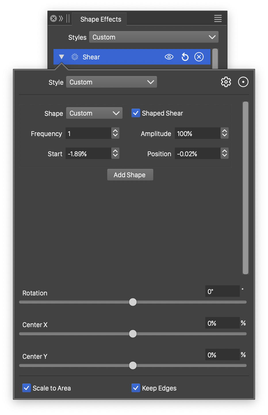
More detailed options of the Shear distortion are available, by clicking on the button.
- Center X and Center Y - Set the center of the distortion shape, relative to the object frame. The center can also be adjusted visually using the primary shape effect editor tool.
- The shear distortion can use multiple shapes to control the amount of point shifting along the shear direction.
- A new shape is added by clicking the Add Shape button.
- If multiple shapes are used, a shape can be removed by clicking on the
 button.
 - Function - Edit the local shear distortion function. This option is visible if the Shaped Shear is not checked. The Edit Curve command opens the function editor view to edit cubic or monotone functions, defining the waving in the distortion.
- Frequency - Set the number of repetitions of the shear distortion function or shape, along the shear direction.
- Amplitude - Set the extent of the shear distortion.
- Start - Set the starting offset of the shape, along the shear direction.
- Position - Set the relative location of the function or shape among multiple shear functions.
- Shaped Shear - Enable or disable the use of shape in the shear distortion.
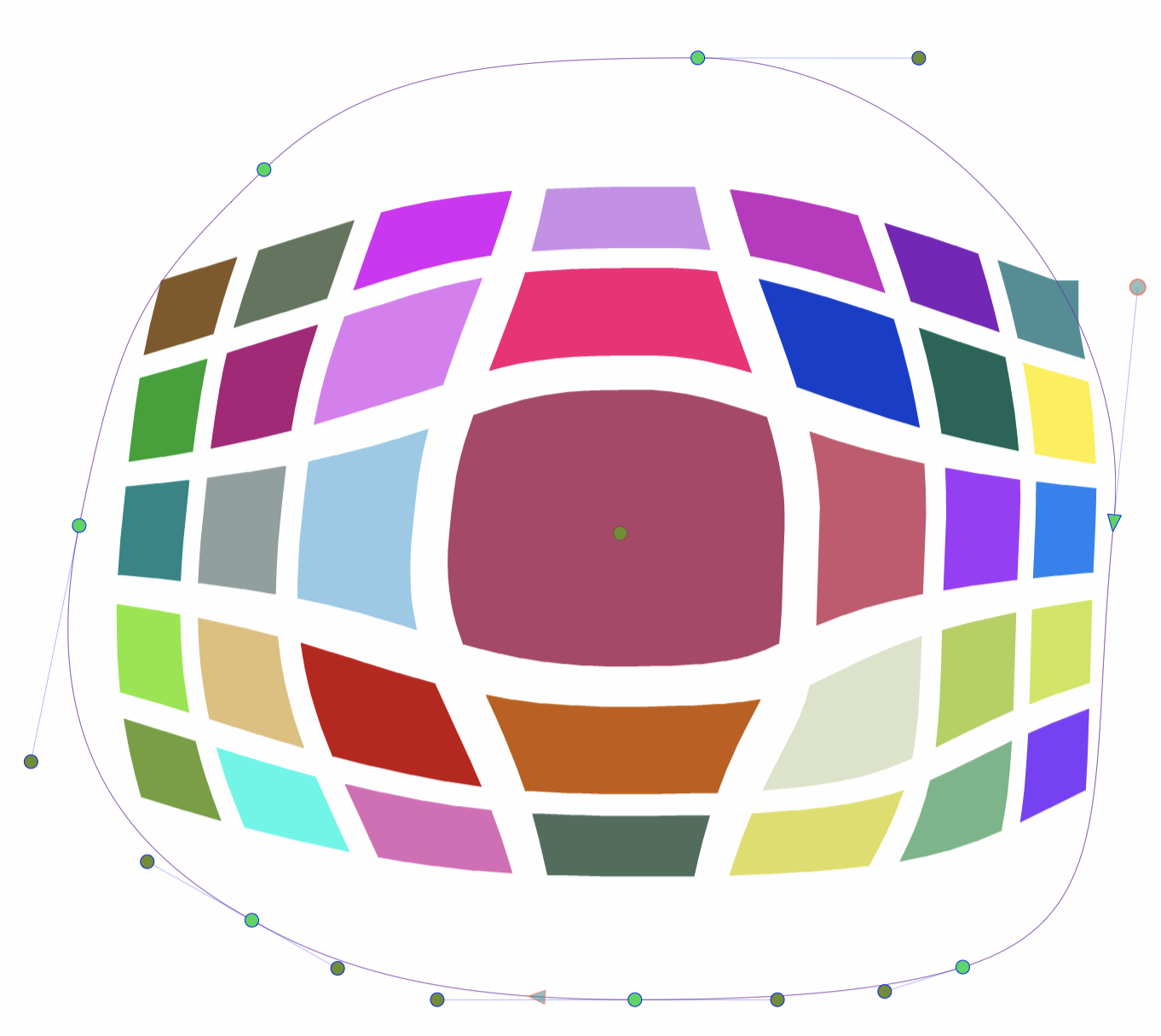
The button from the Shape Effects panel, activates the shape effect tool used to interactively edit the shear distortion attributes.
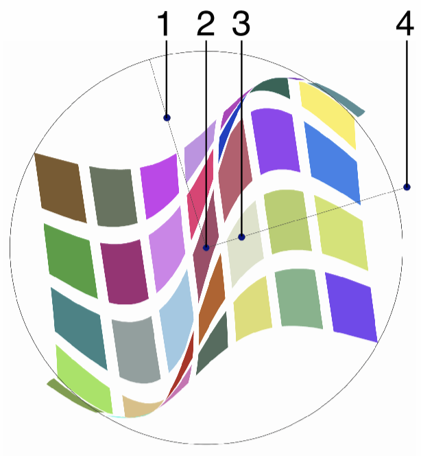
Interactive editing of the Shear distortion.
Interactive editing of the shear distortion is done by dragging the handles to change an attribute value:
- (1) - Adjust the amplitude or strength of the shear distortion.
- (2) - Set the center of the distortion region.
- (3) - Adjust the frequency, or the number of repetitions of the shear distortion function or shape, along the shear direction.
- (4) - Set the rotation of the shear distortion, by dragging this handle around the center.
The shape used in the shear distortion, can be edited as a regular path using the secondary shape effect tool from the icon section of the panel. When the secondary shape effect tool is active, the shape nodes are shown and can be adjusted using regular path editing commands.
Editing the shape of the Shear distortion.
Spikes
The Spikes distortion effect adds concentric spikes at random locations along the object shapes. The variation of the spikes can be controlled by a user editable function.
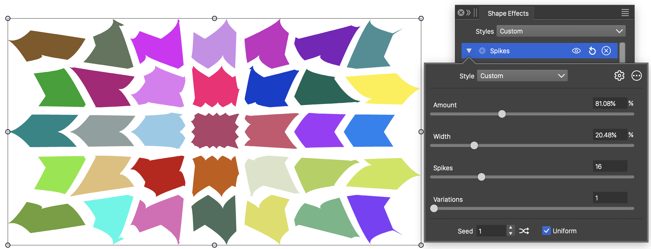
The Spikes distortion, with basic options.
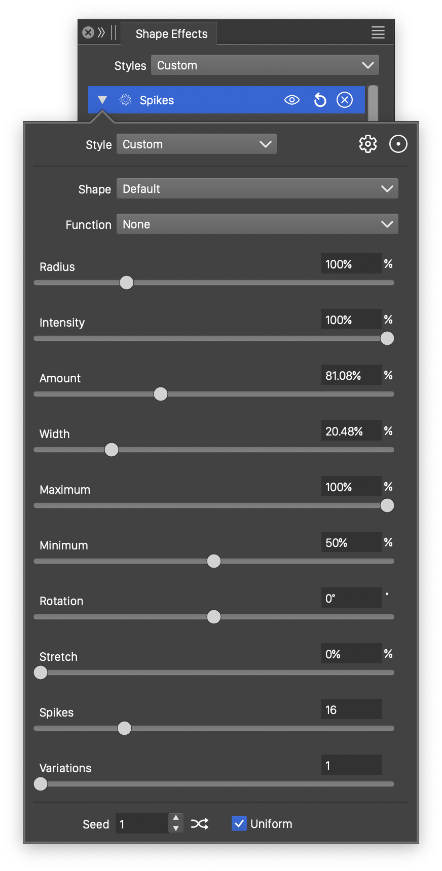
Detailed options of the Spikes distortion.
The Spikes distortion effect uses the following basic options:
- Amount - Edit the strength of the spikes.
- Width - Edit the width of the radial spike region. The width controls the extent of the spikes.
- Spikes - Edit the number of different spike levels.
- Variations - Edit the number of variations in spike lengths.
- Seed - Set the randomization seed used to generate the spikes. The button can be used to pick random seed values.
- Uniform - Enable or disable uniform spikes gaps. When disabled, spikes are positioned randomly. When enabled, the gap between spikes is uniformly distributed.
More detailed options of the Spikes distortion are available, by clicking on the button.
- Shape - Select a shape preset or style, used in the spikes distortion. The shape can be edited using the path editor, by clicking on the button in the icon section of the panel.
- Function - Select the spikes variation function. The spikes variation is a user edited function, controlling the shape of the spikes. The Edit Curve command opens the function editor view to edit cubic or monotone functions, defining the spikes in the distortion.
- Radius - Edit the outer radius of the spikes distortion. The radius determines the distortion area.
- Maximum - Set the maximum spike radius, relative to the available spike width.
- Minimum - Set the minimum spike radius, relative to the available spike width.
- Rotation - Sets the direction of the spikes distortion.
- Stretch - Stretch the spike distortion region vertically.
The button from the Shape Effects panel, activates the shape effect tool used to interactively edit the spikes distortion attributes.
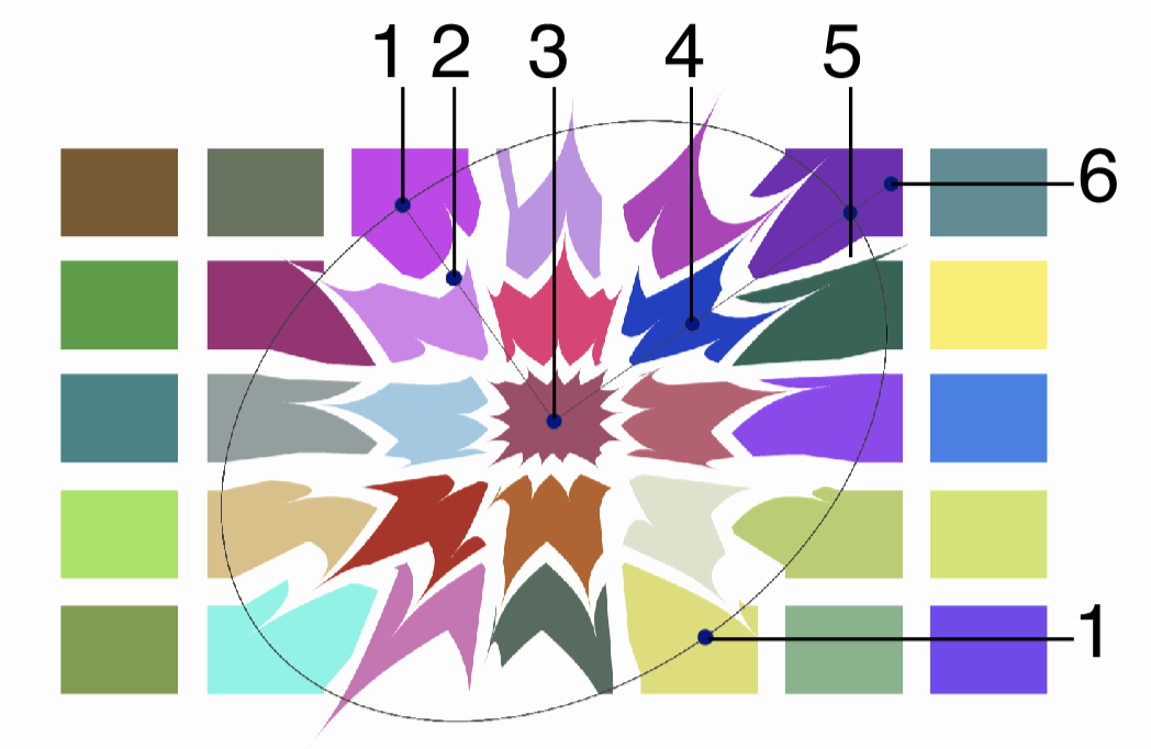
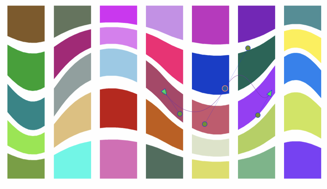
Interactive editing of the Spikes distortion.
Interactive editing of the spikes distortion is done by dragging the handles to change an attribute value:
- (1) - Adjust the vertical stretching of the spikes distortion region.
- (2) - Adjust the strength of the spikes.
- (3) - Set the center of the spikes distortion region.
- (4) - Adjust the width of the radial spike region. The width controls the extent of the spikes.
- (5) - Adjust the radius of the spikes region.
- (6) - Set the rotation of the spikes distortion, by dragging this handle around the center.
The shape used in the spikes distortion, can be edited as a regular path using the secondary shape effect tool from the icon section of the panel. When the secondary shape effect tool is active, the shape nodes are shown and can be adjusted using regular path editing commands.
Editing the shape of the Spikes distortion.
Shaped Lens
The Shaped Lens effect applies a concentric torus lens distortion to the objects. The shaped lens region can be adjusted with a user defined shape.
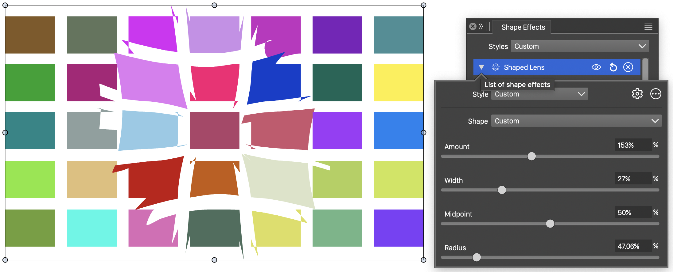
The Shaped Lens distortion, with basic options.
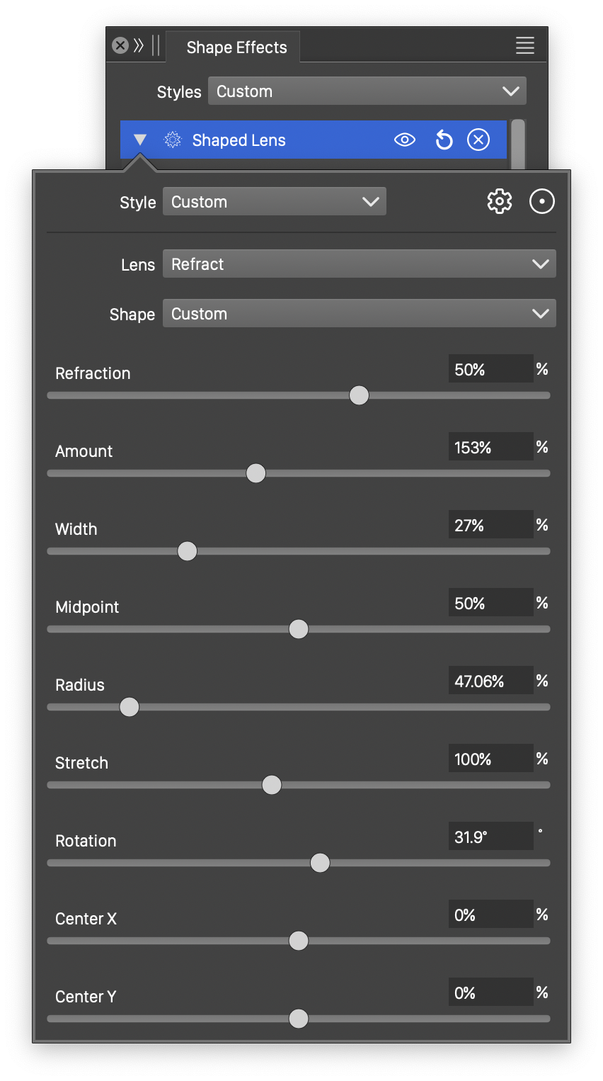
Detailed options of the Shaped Lens distortion.
The Shaped Lens distortion effect uses the following basic options:
- Shape - Select a shape preset or style, used in the shaped lens distortion. The shape can be edited using the path editor, by clicking on the button in the icon section of the panel.
- Amount - Edit the lensing amount.
- Width - Edit the width of the lensing region, relative to the object size.
- Midpoint - Edit the midpoint of the lensing distortion.
- Radius - Edit the radius of the lensing distortion.
More detailed options of the Shaped Lens distortion are available, by clicking on the button.
- Lens - Select the lensing variation function. The lensing variation is a user edited function, controlling the lensing amount. The Edit Curve command opens the function editor view to edit cubic or monotone functions, defining the lensing in the distortion.
- Refraction - Edit the amount of refraction in the lensing effect.
- Stretch - Stretch the torus lensing distortion region vertically.
- Rotation - Sets the rotation of the torus lensing distortion. The rotation is used in non-circular torus lens distortions (stretched to elliptic, or with a user defined shape).
- Center X and Center Y - Set the center of the distortion region, relative to the object frame. The center can also be adjusted visually using the primary shape effect editor tool.
The button from the Shape Effects panel, activates the shape effect tool used to interactively edit the shaped lens distortion attributes.
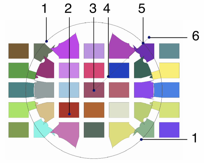
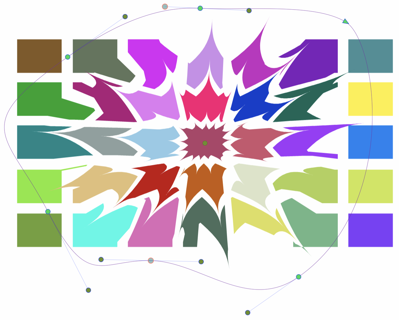
Interactive editing of the Shaped Lens distortion.
Interactive editing of the shaped lens distortion is done by dragging the handles to change an attribute value:
- (1) - Adjust the vertical stretching of the lensing distortion region.
- (2) - Adjust the midpoint of the lensing distortion.
- (3) - Set the center of the lensing distortion region.
- (4) - Adjust the lensing amount.
- (5) - Adjust the radius of the lensing distortion region.
- (6) - Set the rotation of the lensing distortion, by dragging this handle around the center.
The shape used to define the shaped lens distortion region, can be edited as a regular path using the secondary shape effect tool from the icon section of the panel. When the secondary shape effect tool is active, the shape nodes are shown and can be adjusted using regular path editing commands.
Editing the shape of the Shaped Lens distortion.
Twirl
The Twirl distortion effect rotates the points of the shape, using varying rotation angle from the center (large rotation) towards the twirling margin (no rotation). The rotation of the twirl effect can be adjusted interactively.
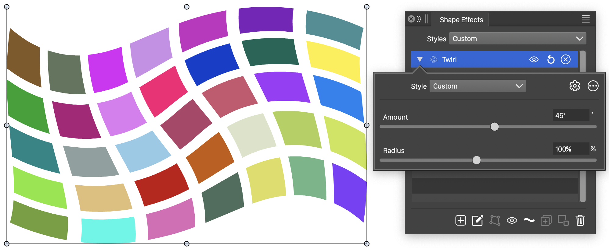
The Twirl distortion, with basic options.
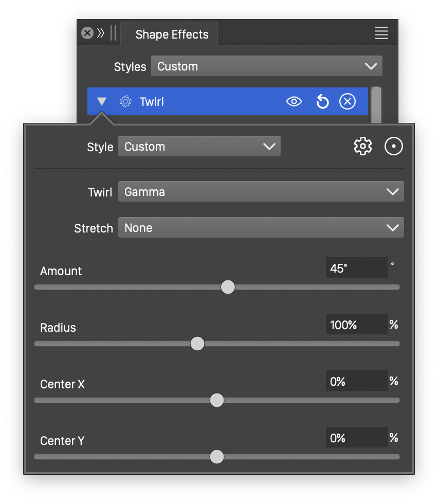
Detailed options of the Twirl distortion.
The Twirl distortion effect uses the following basic options:
- Amount - Set the amount of twirl distortion. This will be the largest rotation angle used at the center of the twirl.
- Radius - Set the radius of the twirl distorted area. The twirl radius determines the distorted region of the object.
More detailed options of the Twirl distortion are available, by clicking on the button.
- Twirl - Select the twirling variation function. The twirling variation is a user edited function, controlling the amount of twirl from the center towards the margin. The Edit Curve command opens the function editor view to edit cubic or monotone functions.
- Stretch - Select the stretching variation function. The stretching variation is a user edited function, controlling the amount of inward and outward stretching of the shapes. The Edit Curve command opens the function editor view to edit cubic or monotone functions.
- Center X and Center Y - Set the center of the twirl distortion region, relative to the object frame. The center can also be adjusted visually using the primary shape effect editor tool.
The button from the Shape Effects panel, activates the shape effect tool used to interactively edit the twirl distortion attributes.
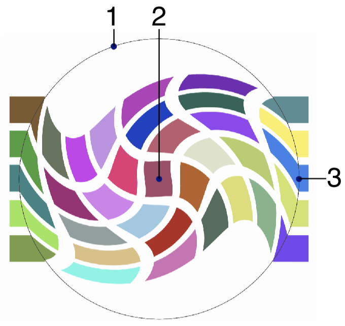
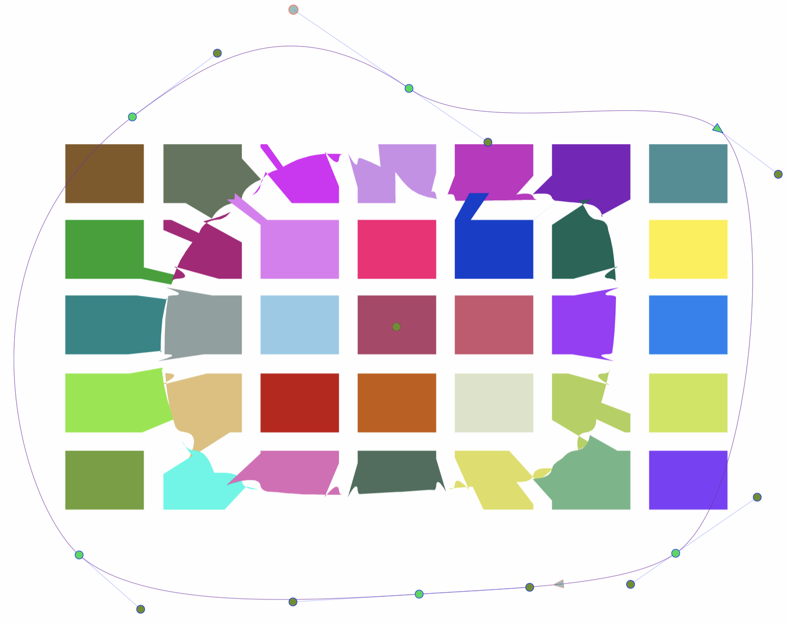
Interactive editing of the Twirl distortion.
Interactive editing of the twirl distortion is done by dragging the handles to change an attribute value:
- (1) - Set the maximum twirling rotation. Drag the handle around the center to increase or decrease the number of revolutions used in the twirl distortion.
- (2) - Adjust the center of the twirl distortion
- (3) - Set the radius of the twirl distortion, by dragging this handle towards or away from the center.
Wave
The Wave distortion effect adds random waving to the object shapes. The Wave distortion is similar to the Noise Wave distortion, except here, there is no noise based local adjustment to the waving strength.
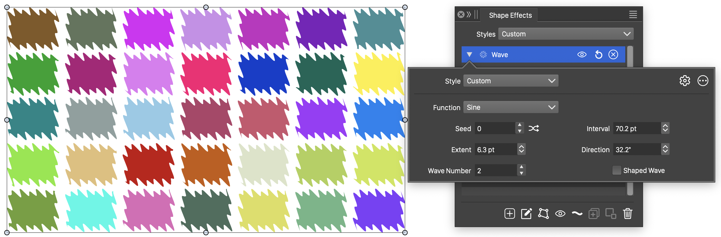
The Wave distortion, with basic options.
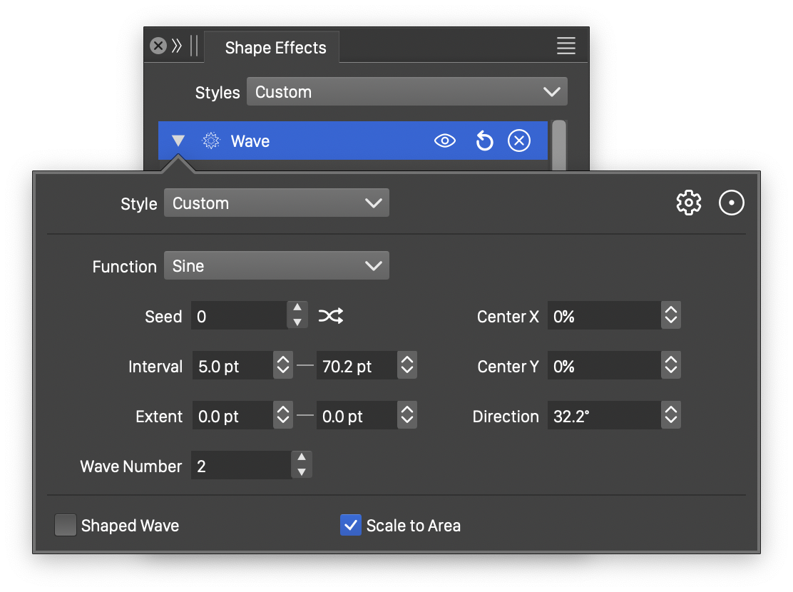
Detailed options of the Wave distortion.
The Wave distortion effect uses the following basic options:
- Function - Edit the wave variation function. This option is visible if the Shaped Wave is not checked. The Edit Curve command opens the function editor view to edit cubic or monotone functions, defining the waving in the distortion.
- Shape - Select a shape preset or style, used for the wave variation. This option is visible if the Shaped Wave is checked. The shape can be edited using the path editor, by clicking on the button in the icon section of the panel.
- Direction - Set the waving direction. The direction can also be adjusted interactively, using the primary shape effect editor tool.
- Max Interval - Set the maximum interval of the waving. Larger values result in longer waves.
- Max Extent - Set the maximum extent of the waving. The amplitude controls the height of a wave.
- Wave Number - Set the number of waves used to create the waving effect.
- Seed - Set the randomization seed used to generate waves. The button can be used to pick random seed values.
- Shaped Wave - Enable or disable the use of a shape (instead of a function) to control the waving distortion. When enabled, the Shape field is used to select a shape preset or style. When disabled, the Function field is used to control the waving.
More detailed options of the Wave distortion are available, by clicking on the button.
- Center X and Center Y - Set the center of the wave distortion, relative to the object frame. The center can also be adjusted visually using the primary shape effect editor tool.
- Min Interval - Set the shortest wave length of the distortion.
- Min Extent - Set the shortest wave extent of the distortion.
- Scale to Area - Enable or disable the scaling of the selected wave shape to the filtered area.
The button from the Shape Effects panel, activates the shape effect tool used to interactively edit the wave distortion attributes.
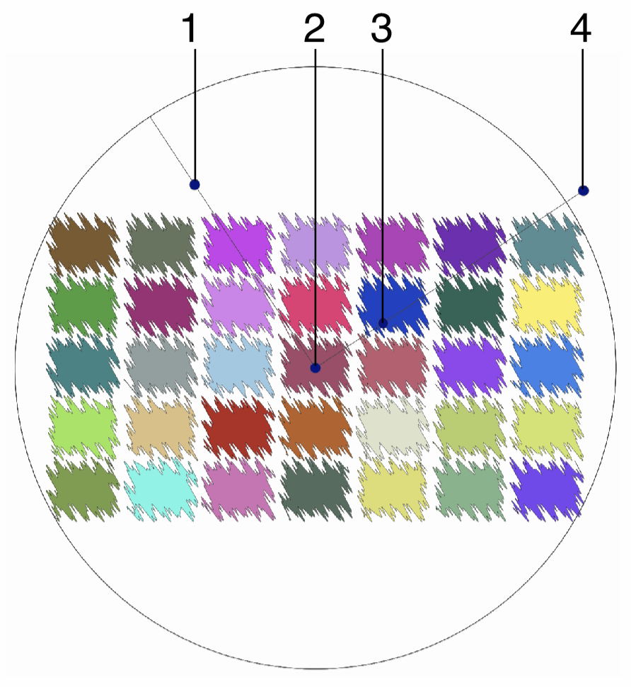
Interactive editing of the Wave distortion.
Interactive editing of the wave distortion is done by dragging the handles to change an attribute value:
- (1) - Adjust the maximum amplitude of the waving.
- (2) - Set the center of the wave distortion.
- (3) - Adjust the maximum interval of the waving.
- (4) - Set the rotation of the wave distortion, by dragging this handle around the center.
The shape used in the wave distortion, can be edited as a regular path using the secondary shape effect tool from the icon section of the panel. When the secondary shape effect tool is active, the wave shape nodes are shown and can be adjusted using regular path editing commands.
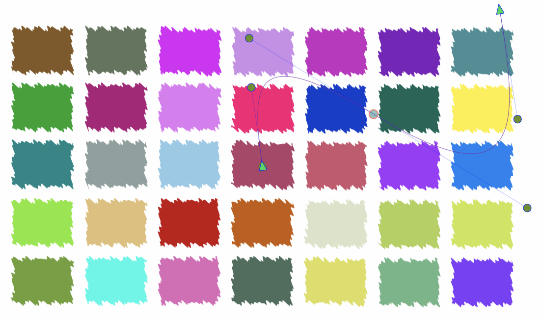
Editing the shape of the Wave distortion.
Wave Bump
The Wave Bump distortion effect stretches the objects towards or away from a user defined wave shape. This stretching is similar to the concentric stretching of Circular Bump and Shape Bump, except in the case of Wave Bump, the direction of the stretching is parallel with a shape.
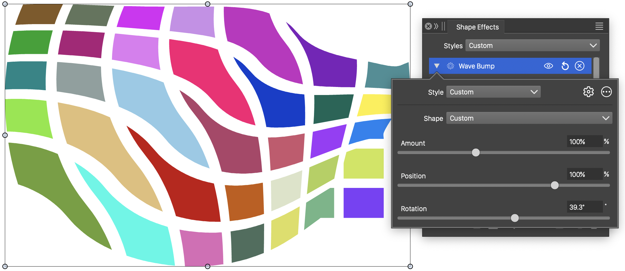
The Wave Bump distortion, with basic options.
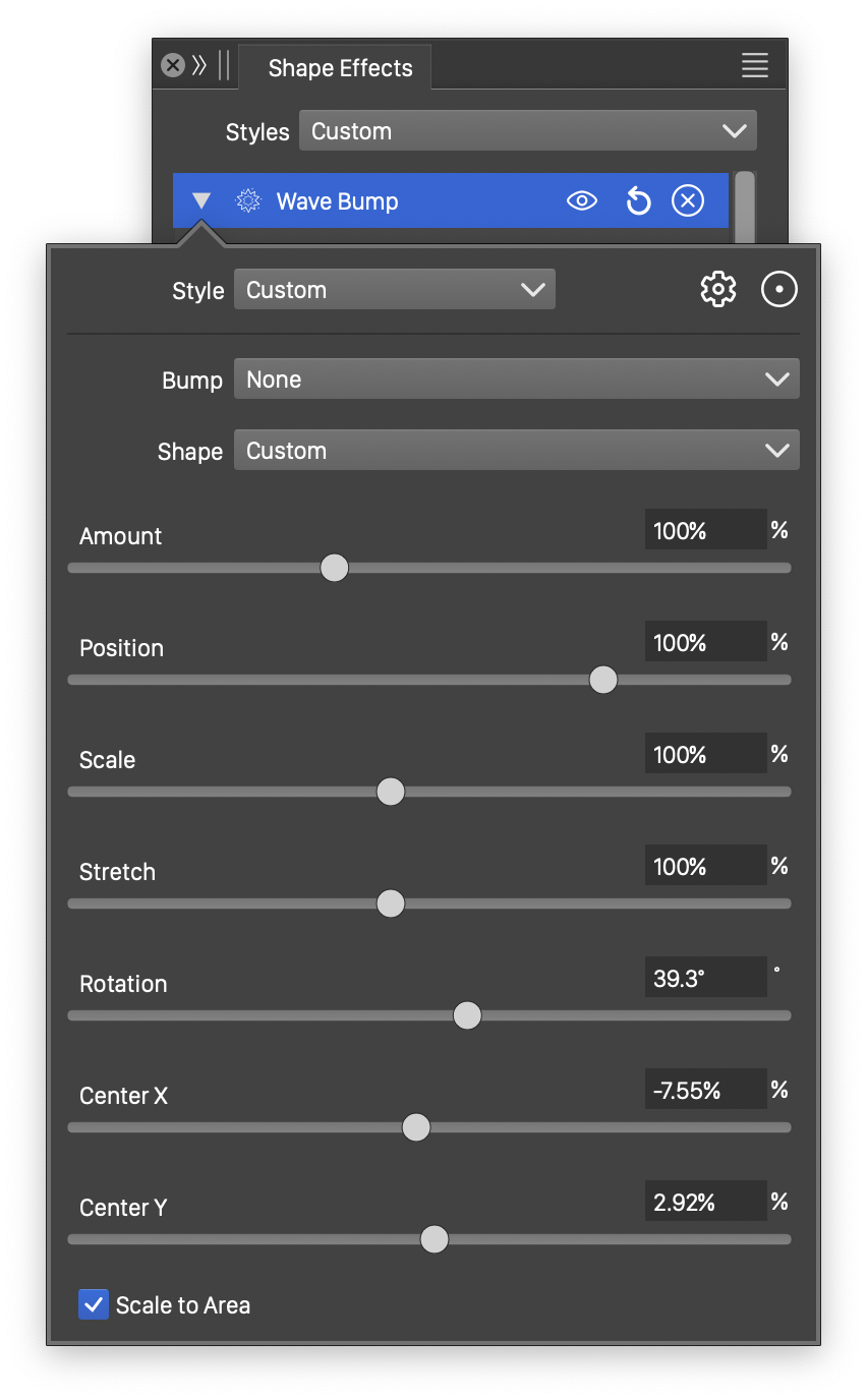
Detailed options of the Wave Bump distortion.
The Wave Bump distortion effect uses the following basic options:
- Shape - Select a shape preset or style, used for the wave bump distortion. The shape can be edited using the path editor, by clicking on the button in the icon section of the panel.
- Amount - Amount of stretching applied parallel to the distortion shape.
- Position - Edit the position of the wave bump distortion.
- Rotation - Set the direction of the wave bump distortion.
More detailed options of the Wave distortion are available, by clicking on the button.
- Bump - Edit the wave bump variation function. The Edit Curve command opens the function editor view to edit cubic or monotone functions, defining the stretching amount in the distortion.
- Stretch - Edit the wave bump region stretching amount.
- Center X and Center Y - Set the center of the wave bump distortion, relative to the object frame. The center can also be adjusted visually using the primary shape effect editor tool.
- Scale to Area - Enable or disable the scaling of the selected wave shape to the filtered area.
The button from the Shape Effects panel, activates the shape effect tool used to interactively edit the wave bump distortion attributes.
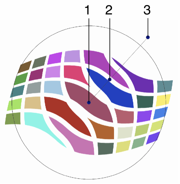
Interactive editing of the Wave Bump distortion.
Interactive editing of the wave bump distortion is done by dragging the handles to change an attribute value:
- (1) - Set the center of the wave distortion.
- (2) - Adjust the strength of the wave bump distortion.
- (3) - Set the rotation of the wave bump distortion, by dragging this handle around the center.
The shape used in the wave bump distortion, can be edited as a regular path using the secondary shape effect tool from the icon section of the panel. When the secondary shape effect tool is active, the wave shape nodes are shown and can be adjusted using regular path editing commands.
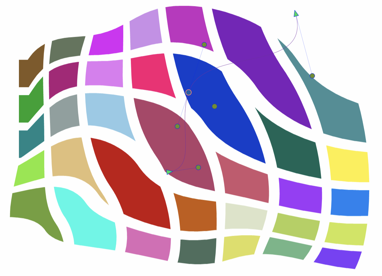
Editing the shape of the Wave Bump distortion.
Zigzag
The Zigzag effect adds a random jagged distortion to the object shapes, at a user selected direction. The Zigzag distortion is similar to the Noise Zigzag distortion, except here, there is no noise adjusting the distortion strength locally.
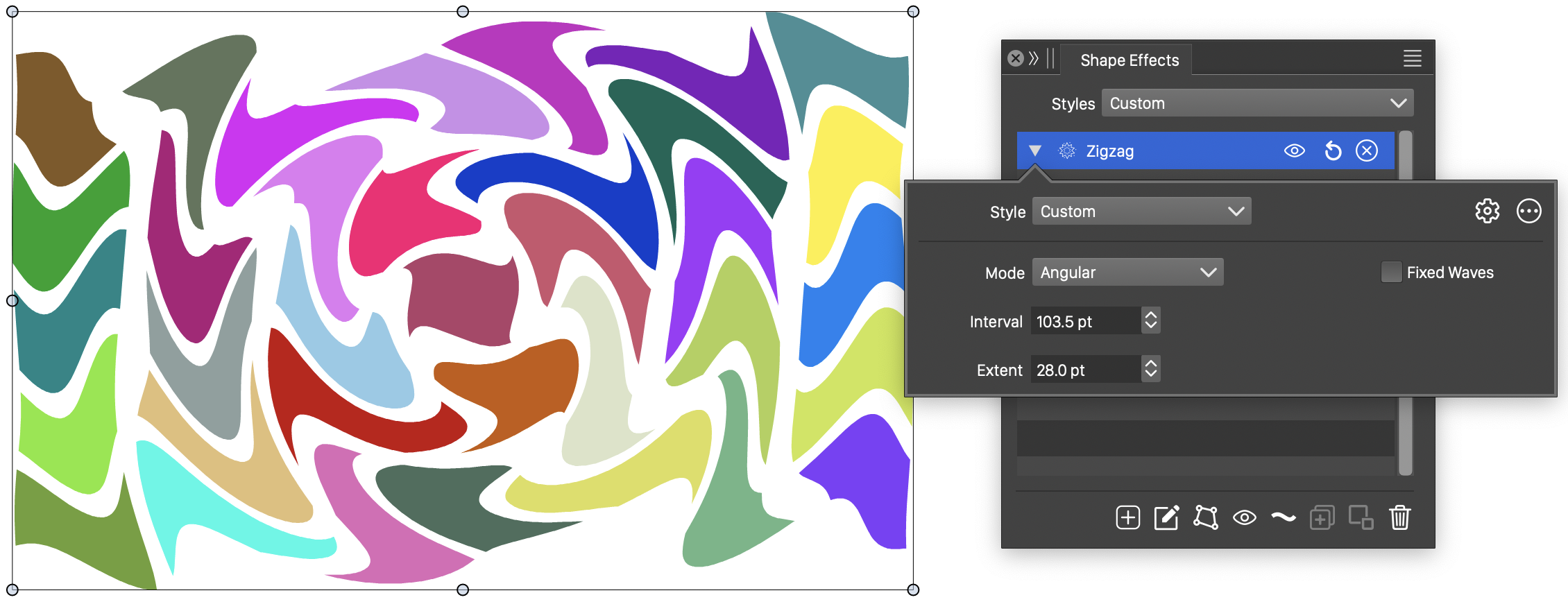
The Zigzag distortion, with basic options.
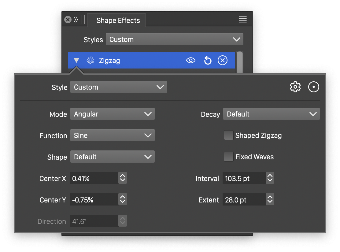
Detailed options of the Zigzag distortion.
The Zigzag distortion effect uses the following basic options:
- Mode - Select the jaggedness mode, controlling the direction of the jagged waves. This can be:
- Angular - The jagged waves are stretching around the center, adjusting the angle, but not the distance, of a shape location relative to the center
- Concentric - The jagged waves are stretching to or from the center, adjusting the distance, but not the angle, of a shape location relative to the center
- Directional - The jagged waves are adjusting the shape at a specific direction, set in the Direction field.
- Wave Number - Set the number of waves. This option is available when the Wave Numbers option is enabled.
- Interval - Set the interval of the waves. Larger values result in longer period of the waves. This option is available when the Wave Numbers option is disabled.
- Extent - Set the extent of the noise jaggedness. The amplitude controls the height of a wave.
- Wave Numbers - Enable or disable the setting of a fixed wave number. When enabled, the number of waves is fixed, regardless of the object size. When disabled, the number of waves is determined by the size of waves.
More detailed options of the Zigzag distortion are available, by clicking on the button.
- Decay - Edit the wave decay function. The Edit Curve command opens the function editor view to edit cubic or monotone functions, defining the amount of decay of the wave extent towards the edge of the region.
- Function - Edit the zigzag variation function. This option is visible if the Shaped Zigzag is not checked. The Edit Curve command opens the function editor view to edit cubic or monotone functions, defining the strength of the jaggedness in the distortion.
- Wave - Select a shape preset or style, used for the zigzag variation. This option is visible if the Shaped Zigzag is checked.
- Shape - Select a shape preset or style, used as the zigzag direction shape. The zigzag shape controls the direction of the jagged waves. The shape can be edited interactively using the path editor, by clicking on the button in the icon section of the panel.
- Center X and Center Y - Set the center of the zigzag distortion, relative to the object frame. The center can also be adjusted visually using the primary shape effect editor tool.
- Direction - Set the zigzag direction. The direction angle is used when the jaggedness mode is set to Directional. The direction can also be adjusted interactively, using the primary shape effect editor tool.
- Shaped Zigzag - Enable or disable the use of a shape (instead of a function) to control the zigzag distortion. When enabled, the Shape field is used to select a shape preset or style. When disabled, the Function field is used to control the jaggedness.
The button from the Shape Effects panel, activates the shape effect tool used to interactively edit the zigzag distortion attributes.
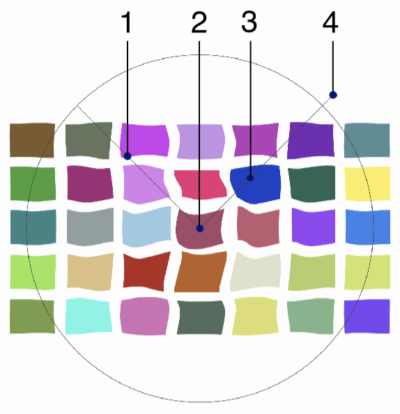
Interactive editing of the Zigzag distortion.
Interactive editing of the zigzag distortion is done by dragging the handles to change an attribute value:
- (1) - Adjust the maximum amplitude of the jaggedness.
- (2) - Set the center of the zigzag distortion.
- (3) - Adjust the maximum interval of the jaggedness.
- (4) - Set the rotation of the zigzag distortion, by dragging this handle around the center.
The shape used in the zigzag distortion, can be edited as a regular path using the secondary shape effect tool from the icon section of the panel. When the secondary shape effect tool is active, the shape nodes are shown and can be adjusted using regular path editing commands.